


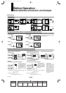
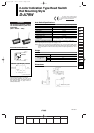
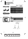
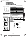

Auto Switch Internal Circuit
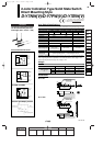
D-J79C
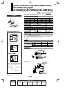
Auto switch model
0.5
3
5
13
52
83
D-J79C
Connector
Lead wire length
(m)
D-J79C
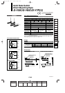
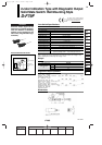
Auto switch model
Wiring type
Output type
Applicable load
Power supply voltage
Current consumption
Load voltage
Load current
Internal voltage drop
Leakage current
Indicator light
D-J79C
2-wire
—
24 VDC Relay, PLC
—
—
24 VDC (10 to 28 VDC)
5 to 40 mA
4 V or less
0.8 mA or less at 24 VDC
Red LED lights when ON.
• Lead wire — Oil resistant vinyl heavy-duty cord, ø3.4, 0.2 mm
2
, 2 cores (Brown, Blue), 0.5 m
Note 1) Regarding the common specifications of the solid state switches, refer to page 12-13-5.
Note 2) Regarding the lead wire length, refer to page 12-13-5.
Auto Switch Specifications
PLC: Abbreviation of Programmable Logic Controller
Weight
(g)
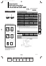
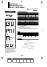
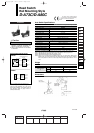
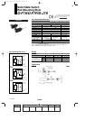
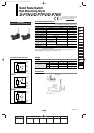
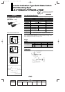
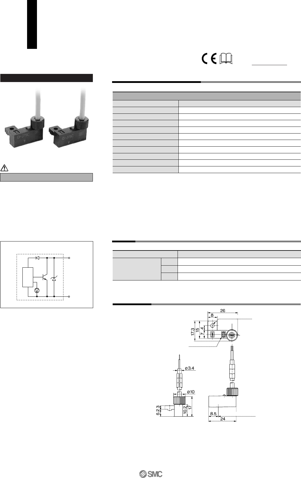
Dimensions
1. Confirm that the connector is appropriately
tightened. If tightened insufficiently, the
waterproof performance will deteriorate.
2. Refer to Best Pneumatics Vol. 6/7/8/9/10
for the details.
Precautions
Solid State Switch
Rail Mounting Style
D-J79C
Main circuit
of switch
OUT (+)
Brown
OUT (–)
Blue
ø3.2 mounting hole
Indicator light
Most sensitive position
Caution
For details about certified products
conforming to international standards,
visit us at www.smcworld.com.
12-13-14
1st
12_13_D-.qxd 04.7.6 18:02 Page 13-14
14