


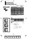

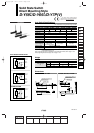
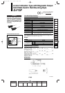
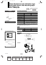
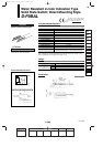
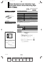
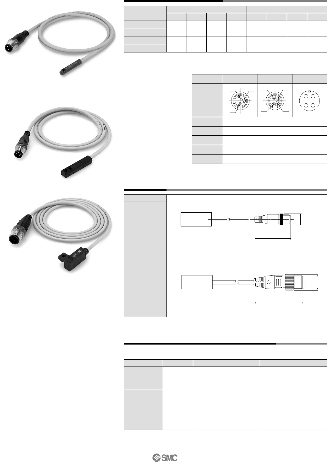
Connector Pin Arrangement
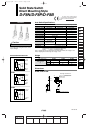
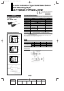
Dimensions
Sensor type
DC 2-wire type
DC 2-wire, Non-polar type
DC 3-wire type
DC 4-wire type
Brown
—
Brown
Brown
1 pin
—
—
—
Orange
2 pin
—
Brown
Blue
Blue
3 pin
Blue
Blue
Black
Black
4 pin
Color distinction of lead wire Meaning of contact number
OUT (+)
—
DC (+)
DC (+)
1 pin
—
—
—
Diagnostic
output
2 pin
—
OUT (±)
DC (–)
DC (–)
3 pin 4 pin
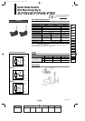
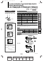
Connection (Female side) Connector Cable
Connector size
M8
M12
Corrence Corporation
OMROM Corporation
Corrence Corporation
OMROM Corporation
Yamatake-Honeywell Co., Ltd.
Hirose Electric Co., Ltd.
DKK Ltd.
M8-3D
M8-4D
XS3
VA-4D
XS2
PA5-4I
HR24
CM01-8DP4S
Manufacturer
3
4
Number of pins
Applicable series example
Connector model
M8—3 pin
4 pin
M12—4 pin
As the parts are not supplied from SMC, refer to the application examples listed in the below.
(For detail such as catalog availability, etc., please contact each manufacturer.)
ø14
44
Sensor section
ø10
31.4
Sensor section
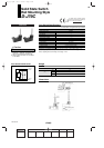
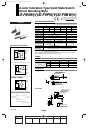
Connector Specifications
Connector model
M8
–
3 pin M8
–
4 pin M12
–
4 pin
JIS C 4524, JIS C 4525, IEC 947-5-2, NECA 0402
300 m/s
2
IP-67 (IEC529 standard)
100 MΩ or more at 500 M VDC
1500 VAC 1 minute (between contacts), Leak current 1 mA or less
12
34
14
3
12
4
3
M8—4 pin
M12—4 pin
OUT (–)
OUT ( )
OUT
OUT
±
M8—3 pin
Pin arrangement
Conformed standard
Impact resistance
Enclosure
Insulation resistance
Withstand voltage
12-13-26
1st
With Pre-wired Connector
12_13_D-.qxd 04.7.6 18:02 Page 13-26
26