


1. Check the specifications.
Read the specifications carefully and use this product
appropriately. The product may be damaged or malfunction if it
is used outside the range of specifications of current current,
voltage, temperature or impact.
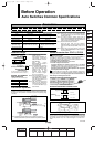
2. Use caution when multiple cylinders are used
and close to each other.
When two or more auto switch cylinders are lined up in close
proximity to each other, magnetic field interference may cause
the switches to malfunction. Maintain a minimum cylinder
separation of 40 mm. (When the allowable interval is specified
for each cylinder series, use the indicated value.)
3. Use caution to the ON time of a switch at the
intermediate position of stroke.
When an auto switch is placed at an intermediate position of
the stroke and a load is driven at the time the piston passes,
the auto switch will operate, but if the speed is too great, the
operating time will be shortened and the load may not operate
properly. The maximum detectable piston speed is:
In cases of high piston speed, the use of an auto switch (D-
F5NT/F7NT/G5NT and M5T) with a built-in OFF delay timer
(≅ 200 ms) makes it possible to extend the load operating time.
4. Wiring should be kept as short as possible.
<Reed switches>
As the length of the wiring to a load gets longer, the rush
current at switching ON becomes greater, and this may
shorten the product’s life. (The switch will stay ON all the time.)
1) For an auto switch without a connect protection circuit, use
a contact protection box when the wire length is 5 m or
longer.
2) Even if an auto switch has a built-in contact protection
circuit, when the wiring is more than 30 m long, it is not able
to adequately absorb the rush current and its life may be
reduced. It is again necessary to connect a contact
protection box in order to extend its life. Please contact
SMC in this case.
<Solid state switches>
3) Although wire length should not affect switch function, use a
wire 100 m or shorter.
5. Use caution to the internal voltage drop of a
switch.
<Reed switches>
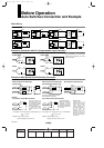
1) Switches with an indicator light (Except D-A56/A76H/A96/
A96V/C76/E76A/Z76)
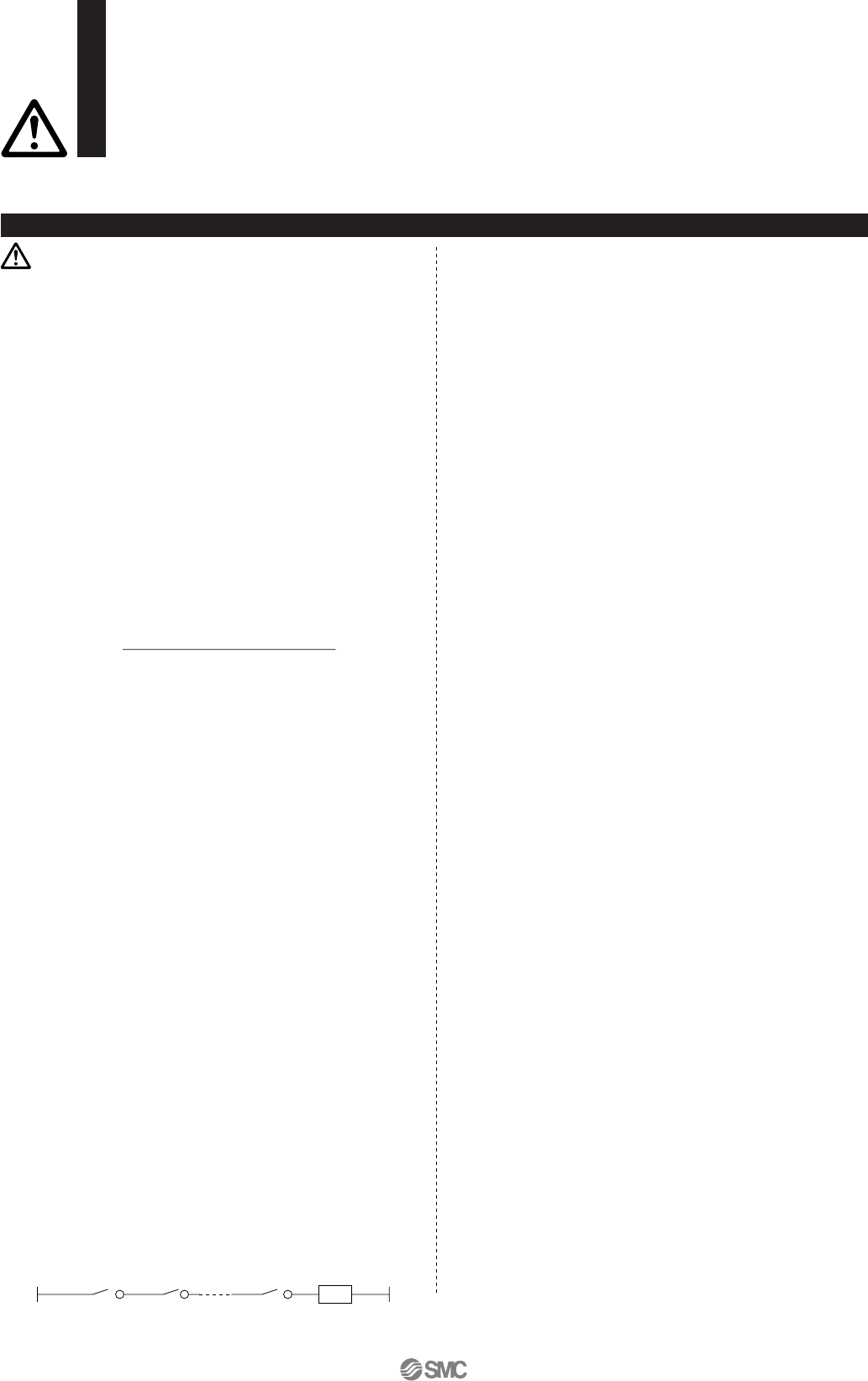
• If auto switches are connected in series as shown below,
take note that there will be a large voltage drop because of
internal resistance in the light emitting diodes. (Refer to
internal voltage drop in the auto switch specifications.)
[The voltage drop will be “n” times larger when “n” auto
switches are connected.]
Even though an auto switch operates normally, the load
may not operate.
• Similarly, when operating below a specified voltage, it is
possible that the load may be ineffective even though the
auto switch function is normal. Therefore, the formula below
should be satisfied after confirming the minimum operating
voltage of the load.
2) If the internal resistance of a light emitting diode causes a
problem, select a switch without an indicator for right
(MODEL D-A6/A80/A80H/A90/A90V/C80/R80/90/E80A/
Z80)
<Solid state switches>
3) Generally, the internal voltage drop will be greater with a 2-
wire solid state auto switch than with a reed switch. Take
the same precautions as in 1).
Also note that a 12 VDC relay is not applicable.
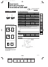
6. Use caution to the leakage current.
<Solid state switches>
With a 2-wire solid state auto switch, current (leakage current)
flows to the load to operate the internal circuit even when in
the OFF state.
If the condition given in the above formula is not met, it will not
reset correctly (stays ON). Use a 3-wire switch if this
specification cannot be satisfied.
Moreover, leakage current flow to the load will be “n” times
larger when “n” auto switches are connected in parallel.
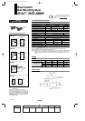
7. Do not use a load that generates surge voltage.
<Reed switches>
If driving a load such as a relay that generates a surge
voltage, use a switch with a built-in contact protection circuit or
use a contact protection box.
<Solid state switches>
Although a zener diode for surge protection is connected at
the output side of a solid state auto switch, damage may still
occur if the surge is applied repeatedly. When a load, such as
a relay or solenoid, which generates surge is directly driven,
use a type of switch with a built-in surge absorbing element.
8. Cautions for use in an interlock circuit
When an auto switch is used for an interlock signal requiring
high reliability, devise a double interlock system to avoid
trouble by providing a mechanical protection function, or by
also using another switch (sensor) together with the auto
switch.
Also perform periodic maintenance inspections and confirm
proper operation.
9. Ensure sufficient space for maintenance
activities.
When designing an application, be sure to allow sufficient
space for maintenance and inspection.
Design and Selection
V (mm/s) =
Auto switch operating range (mm)
Load operating time (ms)
x 1000
Load
Supply
voltage
–
Internal voltage
drop of switch
>
Minimum operating
voltage of load
Current to operate load (OFF condition) > Leakage current
Warning
Auto Switches
Precautions 1
Be sure to read before handling.
For detailed precautions on every series, refer to main text.
12-13-2
1st
12_13_D-.qxd 04.7.6 18:01 Page 13-2
2