


Before Operation
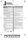
Auto Switches Common Specifications
Auto Switches Common Specifications
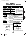
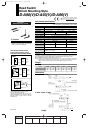
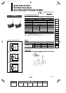
Lead Wire Length
Lead wire length indication
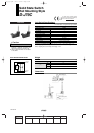
Contact Protection Box:
CD-P11, CD-P12
D-A73
Nil
L
0.5 m
3 m
L
Leakage current
Operating time
Impact resistance
Insulation resistance
Withstand voltage
Ambient temperature
Enclosure
Reed switch
None
1.2 ms
300 m/s
2
1500 VAC for 1 minute
(1)
(Between lead wire and case)
Solid state switch
3-wire: 100 µA or less, 2-wire: 0.8 mA or less
(4)
1 ms or less
(3)
1000 m/s
2
1000 VAC for 1 minute
(Between lead wire and case)
50 MΩ or more at 500 M VDC (Between lead wire and case)
–10 to 60°C
IEC529 Standard IP67, Immersible construction (JIS C 0920)
(2)
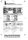
Model
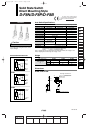
D-LC05
D-LC30
D-LC50
Lead wire length
0.5 m
3 m
5 m
Refer to “Auto Switches Precautions” on pages 12-13-2 to 12-13-4 before handling.
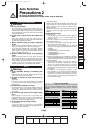
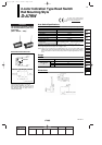
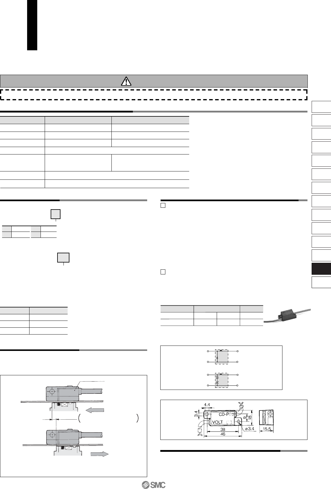
Contact Protection Box Specifications
Load voltage
Max. load current
CD-P11
CD-P12
∗ Lead wire length — Switch connection side 0.5 m
Load connection side 0.5 m
100 VAC or less
25 mA
200 VAC
12.5 mA
24 VDC
50 mA
To connect a switch unit to a contact protection box, connect the lead wire
from the side of the contact protection box marked SWITCH to the lead
wire coming out of the switch unit. Keep the switch as close as possible to
the contact protection box, with a lead wire length of no more than 1
meter.
Contact Protection Box Connection
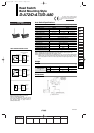
Hysteresis is the distance between the position at which piston movement
operates an auto switch to the position at which reverse movement turns
the switch off. This hysteresis is included in part of the operating range
(one side).
Note) Hysteresis may fluctuate due to the operating environment.
Please contact SMC if hysteresis causes an operational problem.
Auto Switch Hysteresis
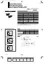
Contact Protection Box/Dimensions
Contact Protection Box Internal Circuit
Surge absorber
Zener diode
CD-P11
CD-P12
Choke
coil
OUT Brown
OUT Blue
OUT (+) Brown
OUT (–) Blue
~
1
<Applicable switch types>
D-A7/A8, D-A7H/A80H, D-A73C/A80C, D-C7/C8, D-C73C/C080C, D-
E7A/E80A, D-Z7/Z8, D-9/9A, D-A9/A9V, and D-A79W type
The above auto switches do not have internal contact protection circuits.
1. Operating load is an inductive load.
2. The length of wiring to the load is 5 m or more.
3. The load voltage is 100 or 200 VAC.
A contact protection box should be used in any of the above
conditions, Unless using a contact protection box, the contact life may
be shortened. (Due to permanent energizing conditions.)
D-A72(H) must be used with the contact protection box regardless
of load styles and lead wire length.
2
Please contact SMC when using built-in contact protection circuit style (D-
A34[A][C], D-A44[A][C], D-A54/A64, D-B54/B64, D-A59W, D-B59W) in the
following conditions: 1. The wiring length to load is more than 30 m; 2.
When using PLC with large flow current.
(Example)
Precautions
Auto switch
Switch
operating
position
(ON)
Hysteresis
Reed switch: 2 mm or less
Solid state switch: 1 mm or less
Switch
operating
position
(OFF)
Note)
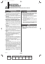
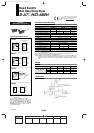
Part no.
Type
Choke
coil
Lead wire length
•
∗ Applicable for the connector
type (D-
C) only.
D-F8PL-
(Example)
Flexible lead wire
specifications
•
61
Z
N
∗
5 m
None
Part No. of Lead Wires
with Connectors
(Applicable only for connector type)
Applicable auto switch with 5
m lead wire (“Z”)
Reed switch: D-B53/B54, D-
C73(C)/C80C, D-A73(C)(H)/
A80C, D-A53/A54, D-Z73, D-
90/97/90A/93A
Solid state switch:
Manufactured upon receipt of
order as standard.
The standard lead wire length
of solid state switches with
timer, water resistant 2-color
indication type, wide range
detection type or heat
resistant 2-color indication
type is 3 meters in length.
(0.5 m is not available.)
Lead wire lengths of 3 m and
5 m are standard for magnetic
field resistant 2-color indicator
type solid state switches. (0.5
m is not available.)
Add “-61” at th end of the part
number for the flexible lead
wire except D-Y59, D-Y69, D-
Y7 and D-M9/M9V type
auto switches.
Note 1)
Note 2)
Note 3)
Note 4)
Electrical entry: Connector type (A73C/A80C/C73C/C80C)
and D-9/9
A/A9/A9V type: 1000 VAC/min. (Between
lead wire and the case)
The following switches, Terminal conduit type (D-
A3/A3
A/A3C/G39/G39A/G39C/K39/K39A/K39C), DIN
terminal type (D-A44/A44A/A44C) and Heat resistant auto
switch (D-F7NJL) meet the IEC529 standard.
IP63, JIS C 0920 Rainproof construction
Except solid state switch with timer (D-M5
TL,
G5NTL/F7NTL/F5NTL) and magnetic resistant 2-color indi-
cation type solid state switch (D-P5DWL). D-J51: 5 ms or
less
Except D-J51 (1 mA or less at 100 VAC, 1.5 mA or less at
200 VAC), D-M5NW/M5PW/M5BW, D-F9BAL, D-P5DWL (1
mA or less at 24 VDC).
Note 1)
Note 2)
Note 3)
Note 4)
(D-Y59, D-Y69, D-Y7 and D-M9/M9V
series use flexible lead wire as srandard. )
12-13-5
1st
MHZ
MHF
MHL
MHR
MHK
MHS
MHC
MHT
MHY
MHW
MRHQ
Misc.
D-
20-
12_13_D-.qxd 04.7.6 18:01 Page 13-5
5