


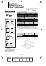
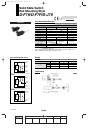

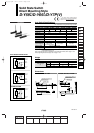
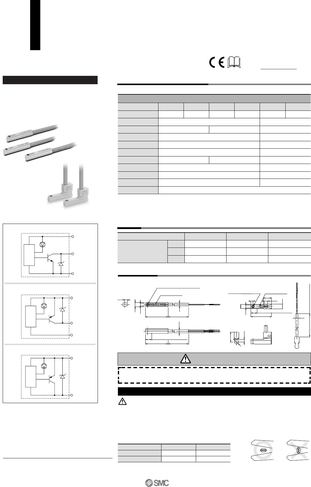
Auto Switch Internal Circuit
D-M9N, D-M9NV
D-M9B, D-M9BV
D-M9P, D-M9PV
Auto switch model
0.5
3
5
D-M9N(V)
8
41
68
D-M9P(V)
8
41
68
D-M9B(V)
7
38
63
Lead wire length
(m)
• Lower load current
• Lead free solder
• Using UL certified (style
2844) lead wire
Grommet
D-M9, D-M9V (With indicator light)
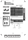
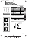
Auto switch model
Electrical entry direction
Wiring type
Output type
Applicable load
Power supply voltage
Current consumption
Load voltage
Load current
Internal voltage drop
Leakage current
Indicator light
D-M9N
In-line
3-wire
NPN
IC circuit, Relay, PLC
5, 12, 24 VDC (4.5 to 28 V)
28 VDC or less
D-M9NV
Perpendicular
D-M9BV
Perpendicular
D-M9PV
Perpendicular
D-M9B
In-line
2-wire
—
24 VDC relay, PLC
—
—
24 VDC (10 to 28 VDC)
2.5 to 40 mA
4 V or less
0.8 mA or less
D-M9P
In-line
PNP
10 mA or less
Red LED lights when ON.
100 µA or less at 24 VDC
D-M9V
D-M9
Auto Switch Specifications
PLC: Abbreviation of Programmable Logic Controller
Weight
(g)
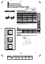
Dimensions
•
Lead wire — Oil resistant vinyl heavy-duty cord, ø2.7 x 3.2 ellipse 0.15 mm
2
, 2 cores (D-M9B), 3
cores (D-M9N, D-M9P)
Note 1) Regarding the common specifications of the solid state switches, refer to page 12-13-5.
Note 2) Regarding the lead wire length, refer to page 12-13-5.
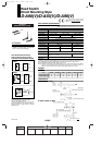
Solid State Switch
Direct Mounting Style
D-M9N
(
V
)
/D-M9P
(
V
)
/D-M9B
(
V
)
Main circuit
of switch
Main circuit
of switch
Main circuit
of switch
OUT
Black
DC (
+)
Brown
DC (
–)
Blue
OUT
Black
DC (
+)
Brown
DC (
–)
Blue
OUT (
+)
Brown
OUT (–)
Blue
—
40 mA or less
0.8 V or less
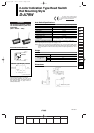
Precautions
During installation, secure the rod cover and tighte
• Over-current protection is not equipped with this product series. When it is
wired incorrectly or a load is short-circuited, a switch may be damaged or
burned.
• In the event of stripping cable sheath, use caution for the stripping direction.
Its insulation may be torn or damaged, depending on the direction.
• Below is given as the recommended tool.
∗ As for 2-wire, a stripper for round shape cord (ø2.0) is usable.
• Fix the switch with appropriate screw installed on the switch body. If using
other screws, switch may be damaged.
Caution on Handling
Caution
Be sure to read before handling. Please contact SMC when using
beyond specifications.
Maker
Product’s name
Part no.
VESSEL Co., Inc.
Tokyo Ideal Co., Ltd.
Wirestripper
Stripmaster
No 3000G
45-089
Operating range shortened, compared to conventional
types.
When replacing conventional types, dependant upon
application, the shortened operating range may cause auto
switch imperceptive.
• When the range of stroke is wider than the operating
range. Example) Stamping, press-fitting, clamping, etc.
• When used to detect intermediate position. (Detection
output time is shortened.)
Note) Please consult with SMC regarding details of
operation range by each actuator.
Since short circuit protection circuit is not built-in, the auto
switch will be immediately damaged when the load is short-
circuited. Be careful not to exchange the power cable
(brown) with the output cable (black).
For details about certified products
conforming to international standards,
visit us at www.smcworld.com.
2.6
4
2.8
M2.5 x 4l slotted set screw
Indicator light
2.7
22
500 (3000)
2.6
4
9.5
500 (3000) (5000)
2.7
4.6
2
20
M2.5 x 4l
Slotted set screw
2.8
8
3.2
4
6
Indicator light
Most sensitive position
3.2
22
500 (3000)
6
Most sensitive position
12-13-16
1st
12_13_D-.qxd 04.7.6 18:02 Page 13-16
16