


1. Do not drop or bump.
Do not drop, bump, or apply excessive impacts (300 m/s
2
or
more for reed switches and 1000 m/s
2
or more for solid state
switches) while handling. Although the body of the switch may
not be damaged, the inside of the switch could be damaged
and cause a malfunction.
2. Do not carry a cylinder by the auto switch lead
wires.
Never carry a cylinder by its lead wires. This may not only
cause broken lead wires, but it may cause internal elements of
the switch to be damaged by the stress.
3. Mount switches using the proper tightening
torque.
When a switch is tightened beyond the range of fastening
torque, the mounting screws or switch may be damaged.
On the other hand, tightening below the range of fastening
torque may alllow the switch to slip out of position. (Refer to
switch mounting for each series regarding switch mounting,
moving, and fastening torque, etc.)
4. Mount a switch at the center of the operating
range.
Adjust the mounting position of an auto switch so that the
piston stops at the center of the operating range (the range in
which a switch is ON). (The mounting positions shown in the
catalog indicate the optimum position at the stroke end.) If
mounted at the end of the operating range (around the
borderline of ON and OFF), the operation will be unstable.
Mounting and Adjustment
1. Avoid repeatedly bending or stretching lead
wires.
Broken lead wires will result from repeatedly applying bending
stress or stretching force to the lead wires.
2. Be sure to connect the load before power is
applied.
<2-wire type>
If the power is turned on when an auto switch is not connected
to a load, the switch will be instantly damaged because of
excess current.
3. Confirm proper insulation of wiring.
Be certain that there is no faulty wiring insulation (contact with
other circuits, ground fault, improper insulation between
terminals, etc.). Damage may occur due to excess current flow
into a switch.
4. Do not wire with power lines or high voltage
lines.
Wire separately from power lines or high voltage lines,
avoiding parallel wiring or wiring in the same conduit with
these lines. Control circuits including auto switches may
malfunction due to noise from these other lines.
5. Do not allow short circuiting of loads.
<Reed switches>
If the power is turned on with a load in a short circuited
condition, the switch will be instantly damaged because of
excess current flow into the switch.
Wiring
Warning
Warning
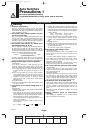
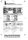
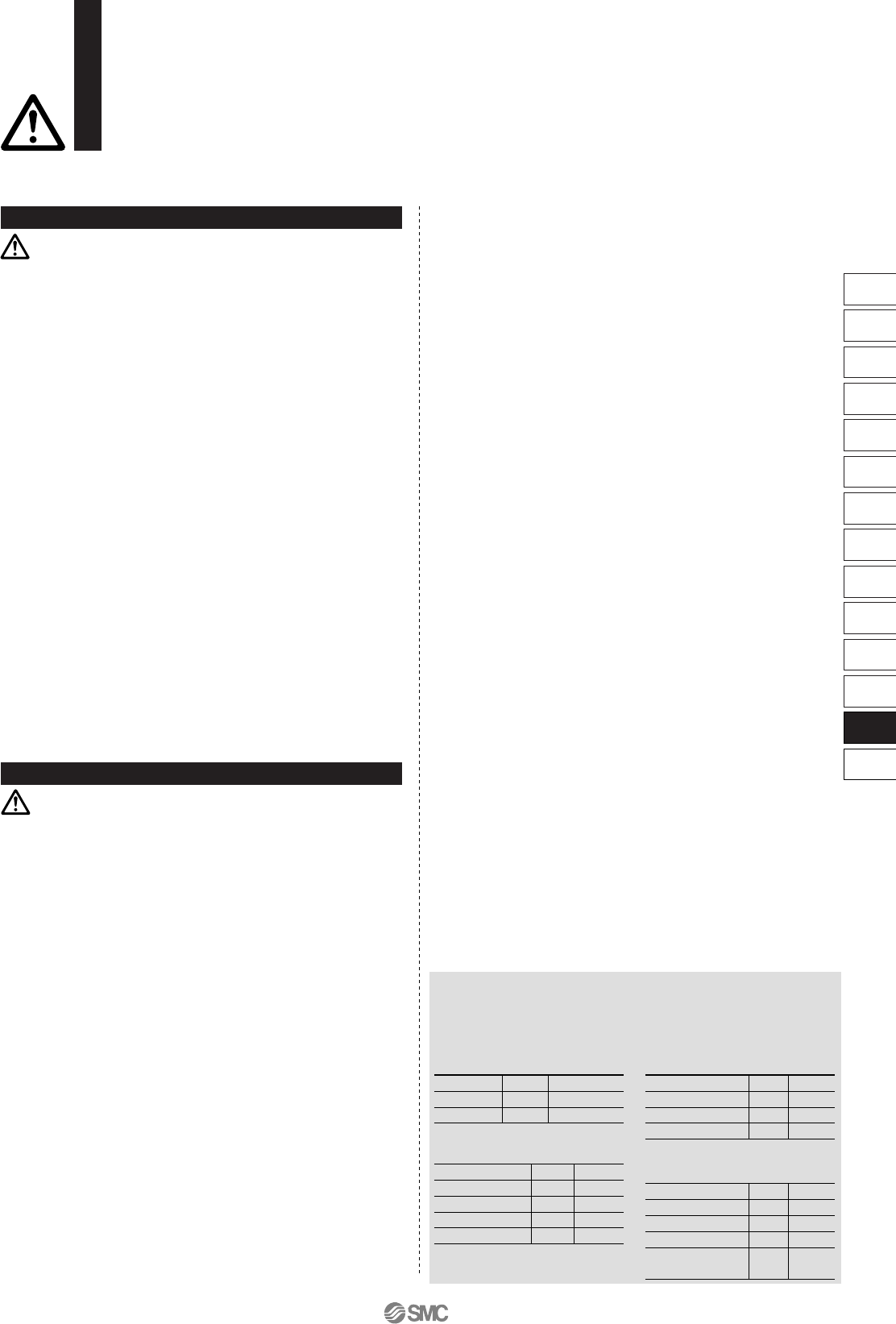
∗ Lead wire color changes
Lead wire colors of SMC auto switches have been changed in
order to meet NECA Standard 0402 for production beginning
September, 1996 and thereafter. Please refer to the tables
provided.
2-wire 3-wire
Solid State
with Diagnostic Output
Solid State with
Latch Type Diagnostic Output
Output (+)
Output (–)
Power supply (+)
Power supply GND
Output
Diagnostic output
Power supply (+)
Power supply GND
Output
Power supply (+)
Power supply GND
Output
Latch type
diagnostic output
Old
Red
Black
New
Brown
Blue
Old
Red
Black
White
Yellow
New
Brown
Blue
Black
Orange
Old
Red
Black
White
Yellow
New
Brown
Blue
Black
Orange
Old
Red
Black
White
New
Brown
Blue
Black
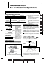
Auto Switches
Precautions 2
Be sure to read before handling.
For detailed precautions on every series, refer to main text.
<Solid state switches>
Model D-F9(Y)/F9W(V)/J51/G5NB and all models of PNP
output switches do not have built-in short circuit prevention
circuits. If loads are short circuited, the switches will be
instantly damaged.
Use caution to avoid reverse wiring with the brown [red] power
supply line and the black [white] output line on 3-wire type
switches.
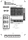
6. Avoid incorrect wiring.
<Reed switches>
A 24 VDC switch with indicator light has polarity. The brown
lead wire or terminal no. 1 is (+), and the blue lead wire or
terminal no. 2 is (–).
[In the case of model D-97, the side without indicator is (+),
and the black line side is (–).]
1) If connections are reversed, a switch will operate, however,
the light emitting diode will not light up.
Also note that a current greater than the maximum
specified one will damage a light emitting diode and make it
inoperable.
Applicable models:
D-A73/A73H/A73C/C73/C73C/E73A/Z73/R73
D-97/93A/A93/A93V
D-A33/A34/A33A/A34A/A44/A44A
D-A53/A54/B53/B54
2) However, when using a two color indication auto switch, the
switch (D-A79W/A59W/B59W), be aware that the switch
will constantly remain ON if the connections are reversed.
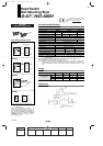
<Solid state switches>
1) If connections are reversed on a 2-wire type switch, the
switch will not be damaged if protected by a protection
circuit, but the switch will always stay in an ON state.
However, it is still necessary to avoid reversed connections,
since the switch could be damaged by a load short circuit in
this condition.
2) If connections are reversed (power supply line (+) and
power supply line (–) on a 3-wire type switch, the switch will
be protected by a protection circuit. However, if the power
supply line (+) is connected to the blue (black) wire and the
power supply line (–) is connected to the black (white) wire,
the switch will be damaged.
12-13-3
1st
MHZ
MHF
MHL
MHR
MHK
MHS
MHC
MHT
MHY
MHW
MRHQ
Misc.
D-
20-
12_13_D-.qxd 04.7.6 18:01 Page 13-3
3