


ECM-3711 Series
34 ECM-3711 Series User’s Manual
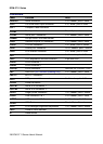
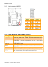
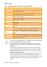
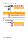
2.4.8.1 Signal Description – Serial Port 2 Connecter (JCOM2)
Signal Signal Description
TxD
Serial output. This signal sends serial data to the communication link. The signal is
set to a marking state on hardware reset when the transmitter is empty or when
loop mode operation is initiated.
RxD Serial input. This signal receives serial data from the communication link.
DTR
Data Terminal Ready. This signal indicates to the modem or data set that the
on-board UART is ready to establish a communication link.
DSR
Data Set Ready. This signal indicates that the modem or data set is ready to
establish a communication link.
RTS
Request To Send. This signal indicates to the modem or data set that the on-board
UART is ready to exchange data.
CTS
Clear To Send. This signal indicates that the modem or data set is ready to
exchange data.
DCD
Data Carrier Detect. This signal indicates that the modem or data set has detected
the data carrier.
RI
Ring Indicator. This signal indicates that the modem has received a telephone
ringing signal.
TxD+/-
Serial output. This differential signal pair sends serial data to the communication
link. Data is transferred from Serial Port 2 Transmit Buffer Register to the
communication link, if the RTS register of the Serial Port 2 is set to LOW.
RxD+/-
Serial input. This differential signal pair receives serial data from the
communication link. Received data is available in Serial Port 2 Receiver Buffer
Register.
DATA+/-
This differential signal pair sends and receives serial data to the communication
link. The mode of this differential signal pair is controlled through the RTS
register of Serial Port 2. Set the RTS register of the Serial Port 2 to LOW for
transmitting, HIGH for receiving.
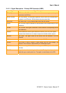
Do not select a mode different from the one used by the connected peripheral,
as this may damage CPU board and/or peripheral.
The transmitter drivers in the port are short circuit protected by a thermal
protection circuit. The circuit disables the drivers when the die temperature
reaches 150 °C.
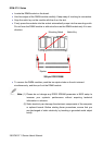
RS-422 mode is typically used in point to point communication. Data and
control signal pairs should be terminated in the receiver end with a resistor
matching the cable impedance (typical 100-120 Ω). The resistors could be
placed in the connector housing.
RS-485 mode is typically used in multi drop applications, where more than 2
units are communicating. The data and control signal pairs should be
terminated in each end of the communication line with a resistor matching the
cable impedance (typical 100-120 Ω). Stubs to substations should be
avoided.