


User’s Manual
ECM-3711 Series User’s Manual
41
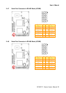
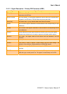
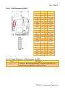
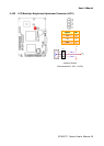
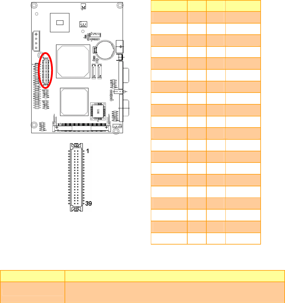
2.4.16 LVDS Connector (JLVDS1)
Signal PIN PIN Signal
+5V 2 1 +3.3V
+5V 4 3 +3.3V
I
2
C_DAT 6 5 I
2
C_CLK
GND 8 7 GND
Txout0 10 9 Txout1
Txout0# 12 11 Txout1#
GND 14 13 GND
Txout2 16 15 Txout3
Txout2# 18 17 Txout3#
GND 20 19 GND
E_Txout0 22 21 E_Txout1
E_Txout0# 24 23 E_Txout1#
GND 26 25 GND
E_Txout2 28 27 E_Txout3
E_Txout2# 30 29 E_Txout3
GND 32 31 GND
Txclk 34 33 E_Txclk
Txclk# 36 35 E_Txclk#
GND 38 37 GND
+12V 40 39 +12V
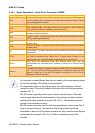
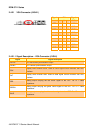
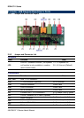
2.4.16.1 Signal Description – LVDS Connector (JLVDS1)
Signal Description
I
2
C_DAT, I
2
C_CLK
I
2
C interface for panel parameter EEPROM. This EERPOM is mounted on the
LVDS receiver. The data in the EEPROM allows the EXT module to automatically
set the proper timing parameters for a specific LCD panel.