


User’s Manual
ECM-3711 Series User’s Manual
43
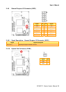
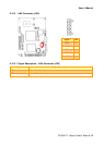
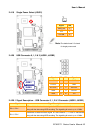
2.4.19 Single Power Select (JSUS1)
Signal PIN
PWR_ON 1
+5V 2
VCCSB 3
Note: The default sets 2-3 closed
for single power used.
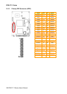
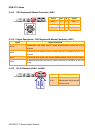
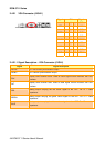
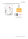
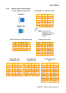
2.4.20 USB Connector 0, 1, 2 & 3 (JUSB1, JUSB2)
Signal PIN PIN Signal
+5V 1 2 GND
D1-/D3- 3 4 GND
D1+/D3+ 5 6 D0+/D2+
GND 7 8 D0-/D2-
GND 9 10 +5V
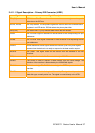
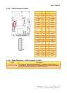
2.4.20.1 Signal Description – USB Connector 0, 1, 2 & 3 Connector (JUSB1, JUSB2)
Signal Signal Description
D0+/-, D2+/-
Differential bi-directional data signal for USB channel 0, 2. Clock is transmitted
along with the data using NRZI encoding. The signalling bit rate is up to 12 Mbs.
D1+/-, D3+/-
Differential bi-directional data signal for USB channel 1, 3. Clock is transmitted
along with the data using NRZI encoding. The signalling bit rate is up to 12 Mbs.
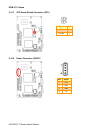
JUSB2
JUSB1