


6
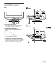
6 AC IN connector (page 7)
This connector provides AC power to the monitor.
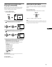
7 Video input connectors (HD15) (y1/y2) (page 6)
These connectors input RGB video signals (0.700 Vp-p,
positive) and sync signals.
* DDC (Display Data Channel) is a standard of VESA.
8 USB (universal serial bus) downstream connectors
(page 8)
Use these connectors to link USB peripheral devices to the
monitor.
9 USB (universal serial bus) upstream connector
(page 8)
Use this connector to link the monitor to a USB compliant
computer.
Setup
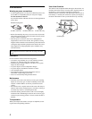
Before using your monitor, check that the following accessories
are included in your carton:
• Power cord (1)
• HD15 video signal cable (the CPD-G420 cable is attached to
the monitor) (1)
• USB cable (1)
• Exclusive Power Mac G3/G4 adapter (1)
• Warranty card (1)
• Notes on cleaning the screen’s surface (1)
• This instruction manual (1)
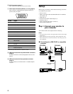
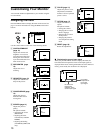
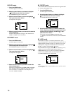
Step 1:Connect your monitor to
your computer
Turn off the monitor and computer before connecting.
Notes
• Do not touch the pins of the video signal cable connector as this might
bend the pins.
• When connecting the video signal cable, check the alignment of the
HD15 connector. Do not force the connector in the wrong way or the
pins might bend.
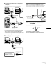
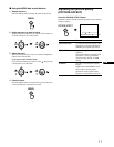
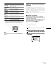
x Connecting to an IBM PC/AT or compatible
computer
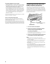
5 4 3 2
1
678910
1112131415
Pin No. Signal
1Red
2 Green (Sync on Green)
3Blue
4 ID (Ground)
5 DDC Ground*
6 Red Ground
7 Green Ground
8 Blue Ground
9 DDC + 5V*
10 Ground
11 ID (Ground)
12 Bi-Directional Data (SDA)*
13 H. Sync
14 V. Sync
15 Data Clock (SCL)*
A
C IN
21
IN
21
video signal cable
(supplied)
IBM PC/AT or compatible
computer
to HD15
CPD-G520 CPD-G420
to video output