


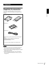

Introduction
Location and Function of Parts and Controls
7
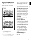
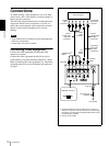
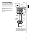
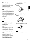
A t INPUT (input signal) connectors (10)
Used to connect the video equipment supplying the
source image.
a) RGB SYNC connectors are equipped only with the UP-
21MD.
B - AC IN connector (10, 11, 12)
Used to connect the printer to a wall outlet with the
supplied power cord.
C Equipotential ground terminal connector (10,
11, 12)
Used to connect to the equipotential plug to bring
the various parts of a system to the same potential.
Refer to “Important safeguards/notices for use in
the medical environments” on page 2.
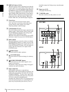
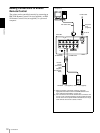
D T OUTPUT connectors (11)
Used to connect the video monitor.
Refer to “Important safeguards/notices for use in
the medical environments” on page 2.
b) RGB SYNC connectors are equipped only with the UP-
21MD.
E RS-232C connector (12)
Used to connect a computer to control the printer.
For details, contact your nearest Sony dealer.
F REMOTE 2 connector (stereo mini jack) (12)
Used to connect a RM-91 Remote Control Unit (not
supplied).
G REMOTE 1 connector (special mini jack) (12)
Used to connect an RM-5500 Remote Control Unit
(not supplied) to be used as a wired remote control
unit.
H NTSC/PAL (NTSC/PAL TV) selector (10, 11)
Set this selector according to the TV system of the
input signal. If you change this setting, turn the
printer power off, then back on again.
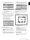
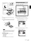
Monitor Display
When the printer is connected to the video monitor and
you first turn on the printer, the following regular screen
message appears.
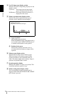
When the MENU button is pressed, the menu screen
displayed.
For detailed information on the menu screen, see “Menu
Tree” on page 39.
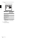
A C (Caption) display section
C is displayed in white when the printer is set to
print a caption.
B Ink ribbon type and remaining amount of ink
ribbon display section
Displays the ink ribbon type and the remaining
amount of ribbon (indicates the number of printouts
that can still be made with the ribbon) when the
ribbon remaining display function is set to ON.
C Message display section
Messages are displayed.
Error messages are displayed on the top line of the
screen.
Warning messages are displayed on the center of
the screen.
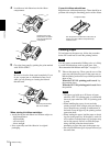
Connector Connectable equipment
RGB SYNC
a)
Video equipment with RGB
SYNC output connectors
S VIDEO Video equipment with a Y/C
separated output connector
VIDEO Video equipment with a
composite video signal output
connector
Connector Connectable equipment
RGB SYNC
b)
Video monitor with RGB SYNC
input connectors
S VIDEO Video monitor with a Y/C
separated input connector
VIDEO Video monitor with a composite
video signal input connector
Selector position When
NTSC NTSC system video equipment is
connected.
PAL PAL system video equipment is
connected.