


Table of Contents
Chapter 1: Introduction ..................................................... 1
Key Features ................................................................................. 1
Unpacking the Mainboard............................................................. 2
Electrostatic Discharge Precautions.............................................. 2
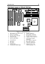
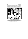
Mainboard Layout w/ Default Settings ......................................... 3
Chapter 2: Hardware Setup.............................................. 5
Jumpers ......................................................................................... 5
JP5: CMOS Clear Jumper ....................................................... 5
JP40: CE Test Jumper Pin ...................................................... 5
JP2: Smart Detect CPU Voltage Function Auto/Manual
Jumper ..................................................................................... 6
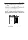
JP37: DIMM Voltage Select Jumper ..................................... 6
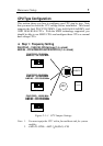
CPU Type Configuration .............................................................. 7
Step 1: Frequency Setting....................................................... 7
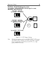
P54C/P55C Ð 75/90/100 CPU Settings (1.5 x clock) ......... 7
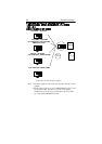
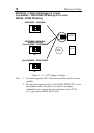
P54C/P55C Ð 100/120/133 CPU Settings (2.0 x clock) ..... 8
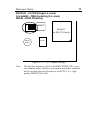
P54C/P55CÐ 150/166 CPU Settings (2.5 x clock) ............. 9
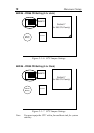
P54C/P55C Ð 180/200 CPU Settings (3.0 x clock) .......... 10
P54C/P55C Ð 233 CPU Settings (3.5 x clock) ................. 11
AMD K6 Ð PR266 CPU Setting (4.0 x clock).................. 12
AMD K6 Ð PR300 CPU Setting (4.5 x Clock)................. 12
Step 2: CPU Single/Dual Voltage Setting............................ 14
Single Voltage CPU Setting ............................................. 14
Dual Voltage CPU Setting................................................ 15
Memory Configuration ............................................................... 15
Memory Configuration Table................................................ 16
RAM Bank Installation Notice.............................................. 16
Cache Configuration ................................................................... 16
Cache Size and RAM Locations ........................................... 16
Multi I/O Port Addresses ............................................................ 17
Connectors .................................................................................. 17
PW2 Ñ ATX Power Supply On/Off Switch Connector
(Momentary Type)................................................................. 17
COM1, COM2 Ñ COM1/COM2 Connectors ...................... 17
JP43: CPU Cooling Fan Connector...................................... 18
FDC Ñ FDC Connector........................................................ 18
ATX PW Ñ ATX Power Supply Connectors....................... 18
RESET Ð Hardware Reset Control........................................ 19
HDD LED Ð HDD LED Connector....................................... 19