


Super Systems Inc. Page 33 SDS Data Logger Manual #4565 Rev D
Firmware Revision 1.10 and above
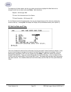
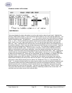
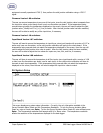
Depending on the revision level of the internal input board, the screen will resemble one of
the two following screens. One version uses one Cold Junction Trim value that is applied to
the entire board. The other version uses a unique Cold Junction Trim value for each of the
five inputs on that board. The instrument will automatically determine which screen should
be displayed based on the internal boards that are installed inside it.
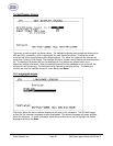
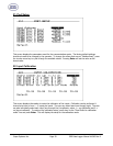
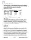
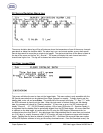
Input Board Version 1.07 and below
This screen displays the setup information to trim the cold junction value of each board.
Note – Since
the Cold Junction screen’s functionality changes slightly based upon the input boards’ version, it is
important to know which version of boards is in the SDS Data Logger.
The input board version number
will be displayed in the top right corner. Highlight the first line (“Select board number”), enter the
desired board number to trim, then press the Enter key. The acceptable values for the board number
are: 1 – 8. Any number entered over 8 will default to 8 and any number entered less than 1 will default
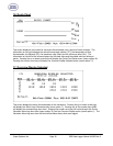
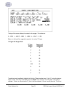
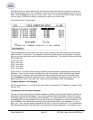
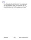
to 1. The next section of the menu screen will look like the following:
Input 5 trim value
Input 4 trim value
Cold Junction Trim
Input 2 trim value
Input 1 trim value
The line for “Input 3 trim value” is shown as “Cold Junction Trim” because this line controls the actual
cold junction trim. Input boards with version 1.07 and below only contain one thermister per board; so
only one cold junction trim will be needed.
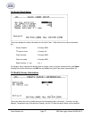
See the section
To Perform a Cold Junction Calibration
below for details on performing the cold junction
calibration. The “Cold Junction Trim” will adjust all of the inputs simultaneously. Any trim value entered
for inputs 5, 4, 2, or 1 will not be reset during the cold junction trim; therefore, those inputs would be
even more offset after the cold junction trim. For best results, perform the cold junction trim first, then
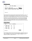
perform any necessary input trims. Press the down arrow key to highlight the “Cold Junction Trim” line.
This will allow an operator to modify a board’s overall cold junction value. Enter the desired cold junction
trim value, and, if necessary, press the circular arrow key to toggle the sign of the cold junction value.
Press the Enter key to begin the cold junction trim. While the system is working, the word “Busy” will
appear below the “Input 1 trim value” line. When the trim has finished, “Busy” will disappear. To set
each individual input’s trim value, press the down arrow key to highlight the specific input. The inputs