


Super Systems Inc. Page 7 SDS Data Logger Manual #4565 Rev D
Getting Started
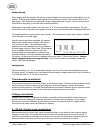
When logging data, the operator will use the on-board display to start and stop the data logging / survey
process. The first steps related to data logging are connecting the inputs to the terminal strips on the
data logger. Each terminal strip represents a single analog board with 5 inputs. You can remove these
terminal strips by pulling up on both ends of the terminal strip.
Depending on the model number, you have either 20 or 40 input channels for data logging. For each
channel there will be a positive and negative connection which must be attached to the appropriate input.
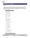
The operator defines an input type for each channel. This is performed through menu option 8 (
Modify
Input Settings
) on the data logger.
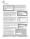
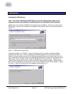
Once the inputs have been connected, the operator
selects which inputs will be included in the survey.
This is done in 2 ways. The template provides
operators with input selection but can be updated on
the data logger using the
Select Input Channel
option.
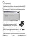
When a template has been selected, the input
channels setup for the template, as defined in the
Template Manager, will be the selected channels for
the survey. As mentioned, this can be updated using menu option 7
Select Input Channel
. Always
select a template prior to running a survey. If you want to create new templates, please see
section
SDS Template Manager
.
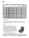
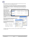
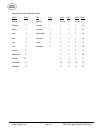
Analog Inputs
The Super Systems, Inc. 31541 Analog Board contains a group of five channels isolated from the main
DC power source. The board can be connected to thermocouples, voltage sources from 20mV full scale to
1.28 Volts full scale, or 4 – 20 mA current loops.
Thermocouple connections
Thermocouple wires can be connected directly to the terminal blocks. The thermocouple junctions should
not be grounded. If they do touch a ground reference, all thermocouples on a board must have a
common ground reference. If multiple thermocouples are connected to different ground reference points,
the accuracy of all thermocouples on the board cannot be guaranteed to be accurate.
Voltage connections
Voltages from 0 mV to 1.28 Volts can be directly connected to the terminal blocks. When measuring
ground-referenced voltages, all references must share a common ground reference. If the voltage
sources are connected to different ground reference points, the accuracy of all the voltage sources
connected to the board need to be checked for accuracy.
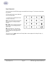
4 – 20 mA. Current Loop connections
Before connecting the current loop, insert the shorting jumper on the board for each channel used to
measure current loops. This jumper inserts the 62-ohm shunt resistor across the input of the A/D. If
multiple current loops are connected to one board, all must share the same power supply and ground
reference points or the accuracy of all the current loops need to be checked for accuracy.