


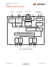
USB 2.0 Hi-Speed 2-Port Hub Controller
Datasheet
SMSC USB2512A 11 Revision 1.96 (07-11-08)
DATASHEET
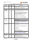
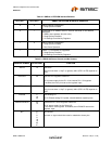
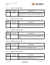
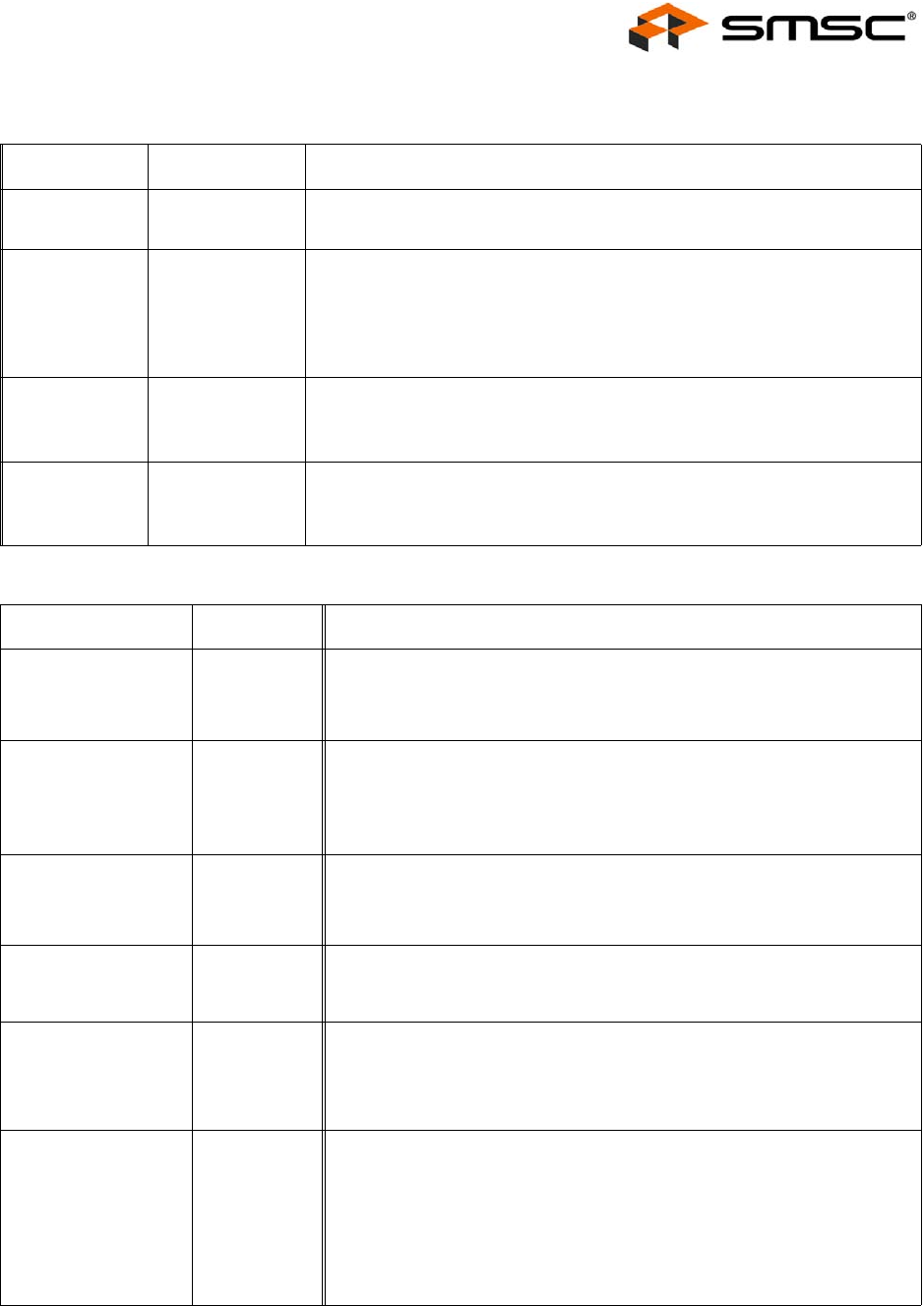
Table 3.2 SMBus or EEPROM Interface Behavior
CFG_SEL1 CFG_SEL0 SMBUS OR EEPROM INTERFACE BEHAVIOR
0 0 Internal Default Configuration
Strap Options Enabled
0 1 Configured as an SMBus slave for external download of user-defined
descriptors.
SMBus slave address 58 (0101100x)
Strap Options Disabled
All Settings Controlled by Registers
1 0 Internal Default Configuration
Strap Options Enabled
Bus Power Operation
112-Wire I
2
C EEPROMS are supported.
Strap Options Disabled
All Settings Controlled by Registers
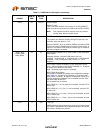
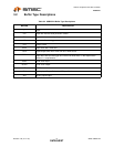
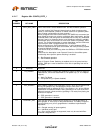
Table 3.3 USB2512A Power, Ground, and No Connect
PACKAGE SYMBOL 36-QFN EMB
FUNCTION
VDD18 14
VDD Core
This pin must have a 1.0μF (or greater) ±20% (ESR <0.1Ω) capacitor to
VSS.
VDD33PLL 36
VDD 3.3 PLL Regulator Reference
+3.3V power supply for the PLL. If the internal PLL 1.8V regulator
is enabled, then this pin acts as the regulator input.
VDDPLL18 34
VDD PLL
This pin must have a 1.0μF (or greater) ±20% (ESR <0.1Ω) capacitor to
VSS.
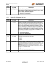
VDDA33 5
10
29
VDD Analog I/O
+3.3V Filtered analog PHY power, shared between adjacent ports.
VDD33/VDD33CR 23
15
VDDIO/VDD 3.3 Core Regulator Reference
+3.3V power supply for the Digital I/O
If the internal core regulator is enabled, then VDD33CR acts as the
regulator input.
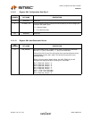
NC 6
7
8
9
18
19
20
21
No Connect
No trace or signal should be routed or attached to these pins.