


USB 2.0 Hi-Speed 2-Port Hub Controller
Datasheet
SMSC USB2512A 13 Revision 1.96 (07-11-08)
DATASHEET
Chapter 4 Configuration Options
4.1 2-Port Hub
SMSC’s USB 2.0 2-Port Hub is fully specification compliant to the Universal Serial Bus Specification
Revision 2.0 April 27,2000 (12/7/2000 and 5/28/2002 Errata). Please reference Chapter 10 (Hub
Specification) for general details regarding Hub operation and functionality.
The 2-Port Hub provides 1 Transaction Translator (TT) that is shared by both downstream ports
(defined as Single-TT configuration), The TT contains 4 non-periodic buffers.
4.1.1 Hub Configuration Options
The SMSC Hub supports a large number of features (some are mutually exclusive), and must be
configured in order to correctly function when attached to a USB host controller. There are three
principal ways to configure the hub: SMBus, EEPROM, or by internal default settings (with or without
pin strapping option over-rides). In all cases, the configuration method will be determined by the
CFG_SEL1 and CFG_SEL0 pins immediately after RESET_N negation.
4.1.1.1 Power Switching Polarity
The hub only supports “active high” port power controllers.
4.1.2 VBus Detect
According to Section 7.2.1 of the USB 2.0 Specification, a downstream port can never provide power
to its D+ or D- pull-up resistors unless the upstream port’s VBUS is in the asserted (powered) state.
The VBUS_DET pin on the Hub monitors the state of the upstream VBUS signal and will not pull-up
the D+ resistor if VBUS is not active. If VBUS goes from an active to an inactive state (Not Powered),
the Hub will remove power from the D+ pull-up resistor within 10 seconds.
4.2 EEPROM Interface
The SMSC Hub can be configured via a 2-wire (I
2
C) EEPROM (256x8). (Please see Table 3.1 for
specific details on how to enable configuration via an I
2
C EEPROM).
The Internal state-machine will (when configured for EEPROM support) read the external EEPROM for
configuration data. The hub will then “attach” to the upstream USB host.
Note: The Hub does not have the capacity to write, or “Program,” an external EEPROM. The Hub only
has the capability to read external EEPROMs. The external eeprom will be read (even if it is blank or
non-populated), and the hub will be “configured” with the values that are read.
Please see Internal Register Set (Common to EEPROM and SMBus) for a list of data fields available.
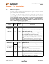
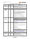
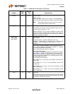
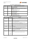
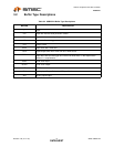
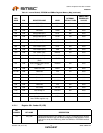
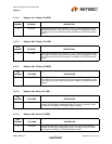
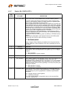
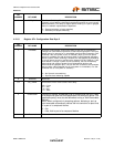
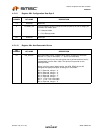
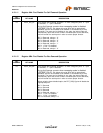
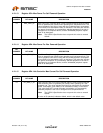
4.2.1 Internal Register Set (Common to EEPROM and SMBus)
Table 4.1 Internal Default, EEPROM and SMBus Register Memory Map
REG
ADDR R/W REGISTER NAME ABBR
INTERNAL
DEFAULT ROM
SMBUS AND
EEPROM OR
VALUES
00h R/W VID LSB VIDL 24h 0x00
01h R/W VID MSB VIDM 04h 0x00
02h R/W PID LSB PIDL 12h 0x00