


USB 2.0 Hi-Speed 2-Port Hub Controller
Datasheet
SMSC USB2512A 21 Revision 1.96 (07-11-08)
DATASHEET
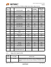
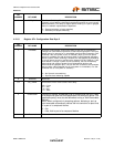
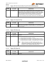
4.2.1.16 Register 0Fh: Hub Controller Max Current For Bus Powered Operation
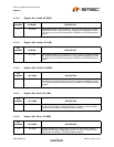
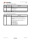
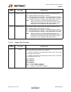
4.2.1.17 Register 10h: Power-On Time
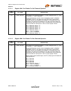
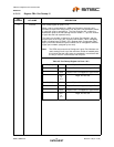
4.2.1.18 Register F6h: Boost_Up
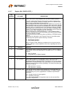
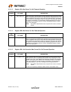
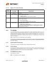
4.2.1.19 Register F8h: Boost_2:0
BIT
NUMBER BIT NAME DESCRIPTION
7:0 HC_MAX_C_BP Hub Controller Max Current Bus-Powered: Value in 2mA increments that the
Hub consumes from an upstream port (VBUS) when operating as a bus-
powered hub. This value will include the hub silicon along with the combined
power consumption (from VBUS) of all associated circuitry on the board.
This value will NOT include the power consumption of a permanently
attached peripheral if the hub is configured as a compound device.
A value of 50 (decimal) would indicate 100mA, which is the default value.
BIT
NUMBER BIT NAME DESCRIPTION
7:0 POWER_ON_TIME Power On Time: The length of time that it takes (in 2 ms intervals) from the
time the host initiated power-on sequence begins on a port until power is
good on that port.
BIT
NUMBER BIT NAME DESCRIPTION
7:2 Reserved Reserved
1:0 BOOST_IOUT USB electrical signaling drive strength Boost Bit for the Upstream Port.
‘00’ = Normal electrical drive strength = No boost
‘01’ = Elevated electrical drive strength = Low (approximately 4% boost)
‘10’ = Elevated electrical drive strength = Medium (approximately 8% boost)
‘11’ = Elevated electrical drive strength = High (approximately 12% boost)
Note: “Boost” could result in non-USB Compliant parameters (one
example would be Test J/K levels), the OEM should use a 00 value
unless specific implementation issues require additional signal
boosting to correct for degraded USB signalling levels.
BIT
NUMBER BIT NAME DESCRIPTION
7:4 Reserved Reserved