


Hi-Speed USB Device PHY with UTMI Interface
Datasheet
Revision 1.5 (11-15-07) 20 SMSC USB3280
DATASHEET
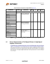
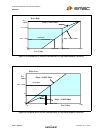
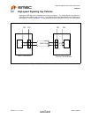
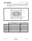
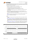
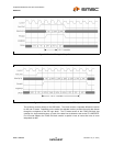
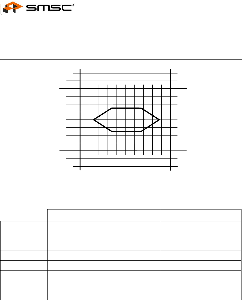
The eye pattern in Figure 6.5 defines the receiver sensitivity requirements for a hub (signal applied at
test point TP2 of Figure 6.3) or a device without a captive cable (signal applied at test point TP3 of
Figure 6.3). The corresponding signal levels and timings are given in the table below. Timings are
given as a percentage of the unit interval (UI), which represents the nominal bit duration for a 480
Mbit/s transmission rate.
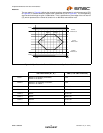
Figure 6.5 Eye Pattern for Receive Waveform and Eye Pattern Definition
VOLTAGE LEVEL (D+, D-) TIME (% OF UNIT INTERVAL)
Level 1 575mV N/A
Level 2 -575mV N/A
Point 1 0V 15% UI
Point 2 0V 85% UI
Point 3 150mV 35% UI
Point 4 150mV 65% UI
Point 5 -150mV 35% UI
Point 6 -150mV 65% UI
Point 1
0%
100%
Point 2
Level 2
Level 1
Point 3 Point 4
Point 5
Point 6
Differential
-400mV
Differential
400mV
Differential
0 Volts