


Hi-Speed USB Device PHY with UTMI Interface
Datasheet
SMSC USB3280 21 Revision 1.5 (11-15-07)
DATASHEET
Chapter 7 Functional Overview
Figure 2.1 on page 7 shows the functional block diagram of the USB3280. Each of the functions is
described in detail below.
7.1 Modes of Operation
The USB3280 supports an 8-bit bi-directional parallel interface.
CLKOUT runs at 60MHz
The 8-bit data bus (DATA[7:0]) is used for transmit when TXVALID = 1
The 8-bit data bus (DATA[7:0]) is used for receive when TXVALID = 0
7.2 System Clocking
This block connects to either an external 24MHz crystal or an external clock source and generates a
480MHz multi-phase clock. The clock is used in the CRC block to over-sample the incoming received
data, resynchronize the transmit data, and is divided down to 60MHz (CLKOUT) which acts as the
system byte clock. The PLL block also outputs a clock valid signal to the other parts of the transceiver
when the clock signal is stable. All UTMI signals are synchronized to the CLKOUT output. The
behavior of the CLKOUT is as follows:
Produce the first CLKOUT transition no later than 5.6ms after negation of SUSPENDN. The
CLKOUT signal frequency error is less than 10% at this time.
The CLKOUT signal will fully meet the required accuracy of ±500ppm no later than 1.4ms after the
first transition of CLKOUT.
In HS mode there is one CLKOUT cycle per byte time. The frequency of CLKOUT does not change
when the PHY is switched between HS to FS modes. In FS mode there are 5 CLKOUT cycles per FS
bit time, typically 40 CLKOUT cycles per FS byte time. If a received byte contains a stuffed bit then
the byte boundary can be stretched to 45 CLKOUT cycles, and two stuffed bits would result in a 50
CLKOUT cycles.
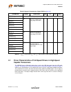
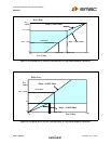
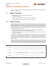
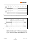
Figure 7.1 shows the relationship between CLKOUT and the transmit data transfer signals in FS mode.
TXREADY is only asserted for one CLKOUT per byte time to signal the SIE that the data on the DATA
lines has been read by the PHY. The SIE may hold the data on the DATA lines for the duration of the
byte time. Transitions of TXVALID must meet the defined setup and hold times relative to CLKOUT.
Figure 7.1 FS CLK Relationship to Transmit Data and Control Signals