


Hi-Speed USB Device PHY with UTMI Interface
Datasheet
SMSC USB3280 9 Revision 1.5 (11-15-07)
DATASHEET
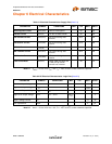
Chapter 4 Interface Signal Definition
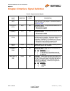
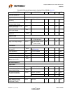
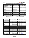
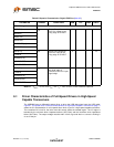
Table 4.1 System Interface Signals
NAME DIRECTION
ACTIVE
LEVEL DESCRIPTION
RESET
(RST)
Input High Reset. Reset all state machines. After coming out of
reset, must wait 5 rising edges of clock before asserting
TXValid for transmit.
See Section 7.8.3
XCVRSELECT
(XSEL)
Input N/A Transceiver Select. This signal selects between the FS
and HS transceivers:
0: HS transceiver enabled
1: FS transceiver enabled.
TERMSELECT
(TSEL)
Input N/A Termination Select. This signal selects between the FS
and HS terminations:
0: HS termination enabled
1: FS termination enabled
SUSPENDN
(SPDN)
Input Low Suspend. Places the transceiver in a mode that draws
minimal power from supplies. Shuts down all blocks not
necessary for Suspend/Resume operation. While
suspended, TERMSELECT must always be in FS mode
to ensure that the 1.5kΩ pull-up on DP remains powered.
0: Transceiver circuitry drawing suspend current
1: Transceiver circuitry drawing normal current
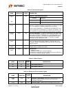
CLKOUT
(CLK)
Output Rising Edge System Clock. This output is used for clocking receive
and transmit parallel data at 60MHz.
OPMODE[1:0]
(OM1)
(OM0)
Input N/A Operational Mode. These signals select between the
various operational modes:
[1] [0] Description
0 0 0: Normal Operation
0 1 1: Non-driving (all terminations removed)
1 0 2: Disable bit stuffing and NRZI encoding
1 1 3: Reserved
LINESTATE[1:0]
(LS1)
(LS0)
Output N/A Line State. These signals reflect the current state of the
USB data bus in FS mode, with [0] reflecting the state of
DP and [1] reflecting the state of DM. When the device is
suspended or resuming from a suspended state, the
signals are combinatorial. Otherwise, the signals are
synchronized to CLKOUT.
[1]
[0] Description
0 0 0: SE0
0 1 1: J State
1 0 2: K State
1 1 3: SE1