


151
APPENDIX
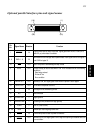
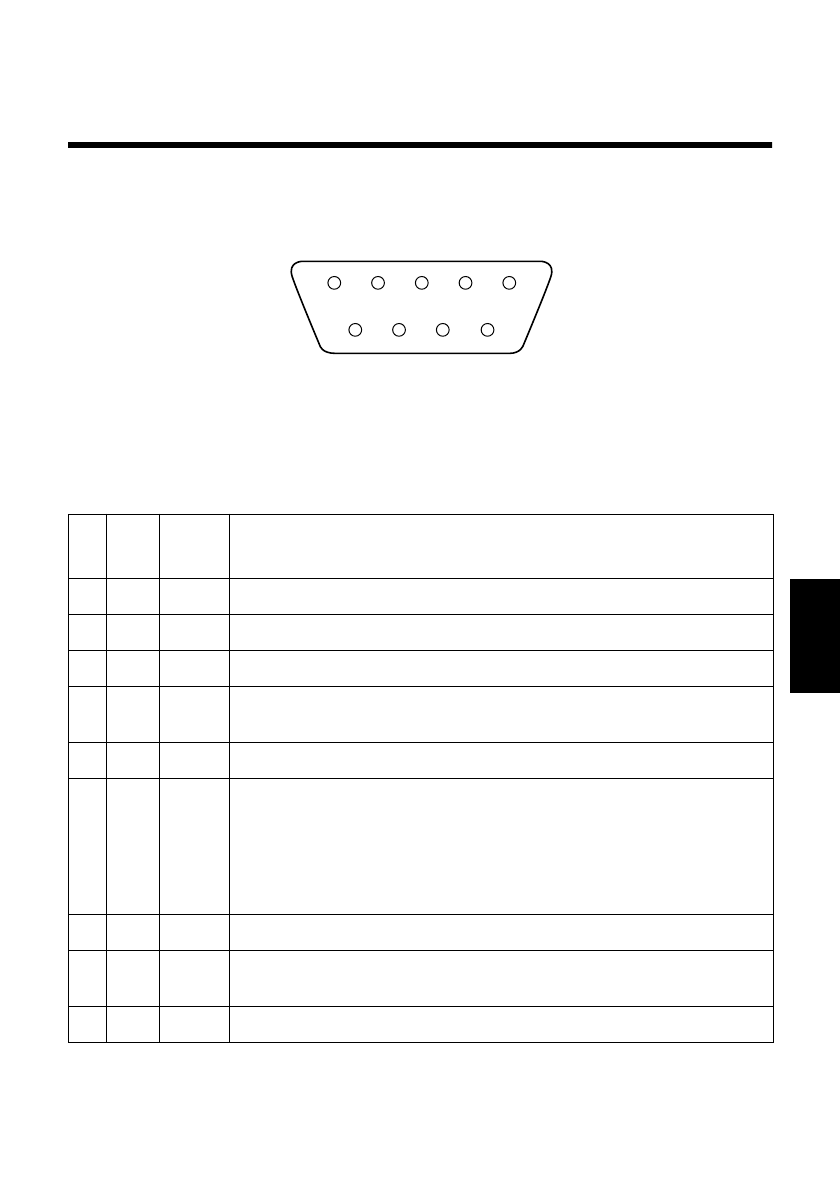
Appendix E: Standard Serial Interface
❏
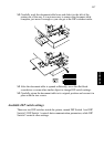
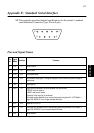
This appendix provides detailed specifications for the printer’s standard
serial interface (Connector Type: D-sub 9-pin).
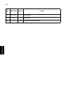
Pins and Signal Names
Pin
No.
Signal
Name
Direction Function
1 FG — Frame Ground
2 RXD IN Receive data
3 TXD OUT Transmission data
4 DTR OUT Data terminal ready signal. This signal changes to SPACE when the printer is ready to
receive data.
5 SG — Signal ground
6 DSR IN Signal line that indicates if the host computer can receive data.
SPACE: host can receive
MARK: host cannot receive
The status of this signal is not confirmed.
This signal can be specified as an internal reset signal using Switch 7 of DIP Switch 1
(page 148). MARK of 1ms or longer activates the reset.
7 RTS OUT Same as DTR (Pin 4).
8 INIT IN This signal can be specified as an internal reset signal using Switch 8 of DIP Switch 1
(page 148). SPACE of 1ms or longer activates the reset.
9 N/C — Not connected
51
6
9