


154
APPENDIX
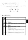
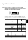
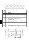
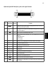
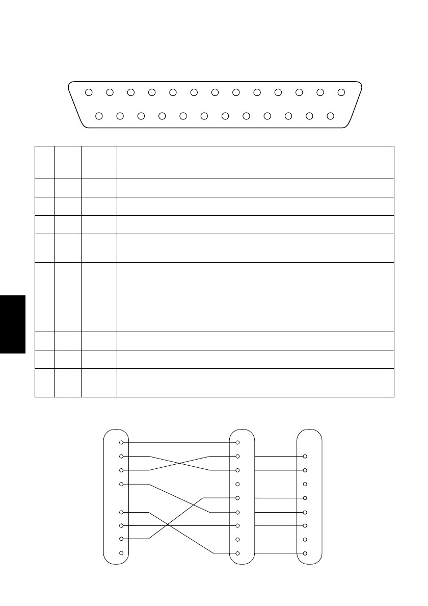
Optional serial interface pins and signal names
Pin
No.
Signal
Name
Direction Function
1 FG — Frame Ground
2 TXD OUT Transmission data
3 RXD IN Receive data
4 RTS OUT Data terminal ready signal. This signal changes to SPACE when the printer is ready to
receive data.
6 DSR IN Signal line that indicates if the host computer can receive data.
SPACE: host can receive
MARK: host cannot receive
The status of this signal is not confirmed.
This signal can be specified as an internal reset signal using of DIP Switch 7 (page 153).
MARK of 1ms or longer activates the reset.
7 SG — Signal ground
20 DTR OUT Same as RTS (Pin 4).
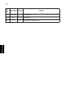
25 INIT IN This signal can be specified as an internal reset signal using of DIP Switch 8 (page 153).
SPACE of 1ms or longer activates the reset.
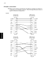
13
25
1
14
1
2
3
4
6
1
2
3
4
5
6
7
8
20
F-GND
TXD
RXD
RTS
DSR
20
25
7
S-GND
DTR
INIT
Printer side
(D-sub 25 pin)
IBM PC side
3
2
7
8
6
5
1
4
F-GND
TXD
RXD
RTS
CTS
DSR
S-GND
DCD
DTR
9 pin25 pin