


ADJUSTMENT
3-4
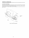
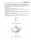
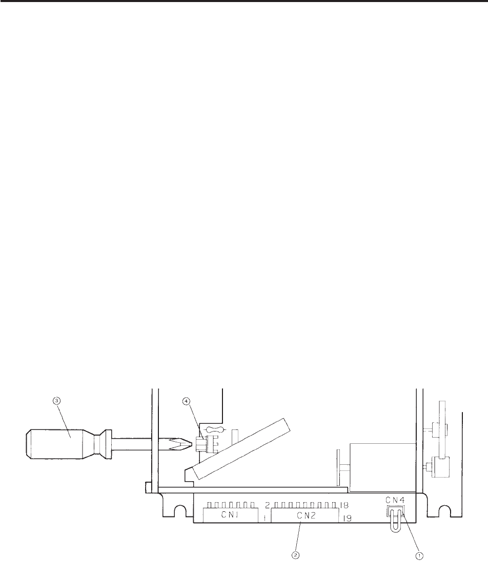
3.3 Adjusting the Print Speed
The printing speed is critical to ensure maximum reliability of the printer.
If the printing is too fast, the print head cannot keep up and the wires get caught on the ribbon.
1. Remove the printer mechanism according to the procedure described in Section 4.2.
2. Leave the ribbon cartridge installed.
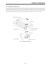
3. To disable the cover open detector, connect Pins 1 and 2 of connector CN4 1 together (for example by putting
a clip between them).
4. Apply the voltages shown below to the pins of printer mechanism connector CN2 2. The carriage motor turns
and the carriage moves left or right.
Pin No. 7 (or No. 8) .......24 VDC
Pin No. 9 (or No. 10) .....Ground
Pin No. 12 ..... 5 VDC
Pin No. 18 ..... Ground
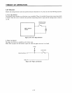
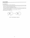
5. The printing speed is calculated from the timing signal frequency.
Connect the measurement terminals of the frequency counter to connector CN2 2 as indicated below and
measure the timing signal frequency.
Pin No. 16 ..... frequency counter input terminal
Pin No. 18 ..... ground
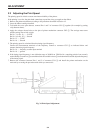
6. If the timing signal frequency is not within the range of 1600 Hz to 1700 Hz (for a sampling period of one second),
use the Phillips screwdriver 3 to turn the knob for the variable resistor 4 on the terminal board and adjust the frequency
of the timing signal.
7. Remove the connector between Pins 1 and 2 of connector CN4 1 and install the printer mechanism on the
main unit by reversing the procedure with which you removed it.
Fig. 3-6 Print Speed Adjustment