


PARTS LIST
6-41
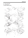
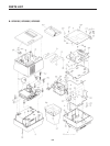
6.1 Printer Assembly 6-1
6.1.1 Assembly Drawing ....................... 6-1
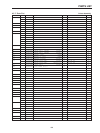
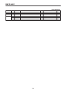
6.1.2 Parts List........................................ 6-3
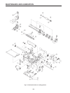
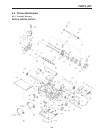
6.2 Printer Mechanism 6-5
6.1.1 Assembly Drawing ....................... 6-5
6.2.2 Parts List........................................ 6-6
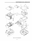
6.3 Sub-assembly 6-8
6.3.1 Upper Case Unit............................ 6-8
6.3.2 Lower Case Unit ........................... 6-9
6.4 Wiring Schematic of Printer 6-10
6.4.1 For Serial Interface ....................... 6-10
6.4.2 For Parallel Interface..................... 6-11
6.5 Main Logic Board 6-12
6.5.1 Serial Interface .............................. 6-12
6.5.1.1 Circuit Diagram........................ 6-12
6.5.1 Component Layout....................... 6-16
6.5.1.3 Parts List................................... 6-17
6.5.2 For Parallel Interface..................... 6-20
6.5.2.1 Circuit Diagram........................ 6-20
6.5.2.2 Component Layout.................. 6-24
6.5.2.3 Parts List................................... 6-25
6.6 Control Panel Board 6-28
6.6.1 Circuit Diagram ............................. 6-28
6.6.2 Component Layout....................... 6-28
6.6.3 Parts List........................................ 6-28
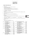
CHAPTER 6
PARTS LIST
HOW TO USE PARTS LIST
1. DRWG. NO.
This column shows the drawing number of the illustration.
2. REVISED EDITION MARK
This column shows a revision number.
Part that have been added in the revised edition are indicated with “#”.
Part that have been abolished in the revised edition are indicated with “*”.
#1 : First edition → Second edition
*1 : First edition → Second editon
3. PARTS NO.
Parts numbers must be indicated when ordering replacement parts. Parts described as “NPN” have no parts
number and are not in stock, i.e., unavailable.
4. PARTS NAME
Parts names must be indicated when ordering replacement parts.
5. Q’TY
This column shows the number of the part used indicated in the figure.
6. REMARKS
Where there are differences in the specifications of the fuse, destinations, etc., the differences are described in
words or indicated by two letters.
US … U.S.A. EC … EC UK … Unied Kingdom HK … Hong Kong
The seal number of ROM is described in this column. The “**” mark of seal number is variable depending on
the software version.
7. RANK
Parts marked “S” are service parts.
Service parts are recommended for maintenance.
6.7
Power Supply Unit (Except for H.K.)
6-29
6.7.1 Circuit Diagram ............................. 6-29
6.7.2 Component List ............................ 6-30
6.7.3 Parts List........................................ 6-31
6.8 Power Supply Unit (For H.K.) 6-32
6.8.1 Circuit Diagram ............................. 6-32
6.8.2 Parts List........................................ 6-33
6.9 Terminal Board 6-34
6.9.1 Circuit Diagram ............................. 6-34
6.9.2 Component List ............................ 6-35
6.9.3 Parts List........................................ 6-36
6.10 Home Position Detector Board 6-37
6.10.1 Circuit Diagram ............................. 6-37
6.10.2 Component Layout ....................... 6-37
6.10.3 Parts List ........................................ 6-37
6.11
R422 Interface Board (BD320K): option
6-38
6.11.1 Circuit Diagram ............................. 6-38
6.11.2 Component Layout ....................... 6-38
6.11.3 Parts List ........................................ 6-38
6.12
Current Loop Board (BD320L): option
6-39
6.12.1 Circuit Diagram ............................. 6-39
6.12.2 Component Layout ....................... 6-39
6.12.3 Parts List ........................................ 6-39
6