


PARTS REPLACEMENT
4-7
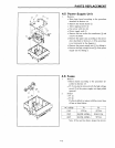
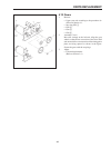
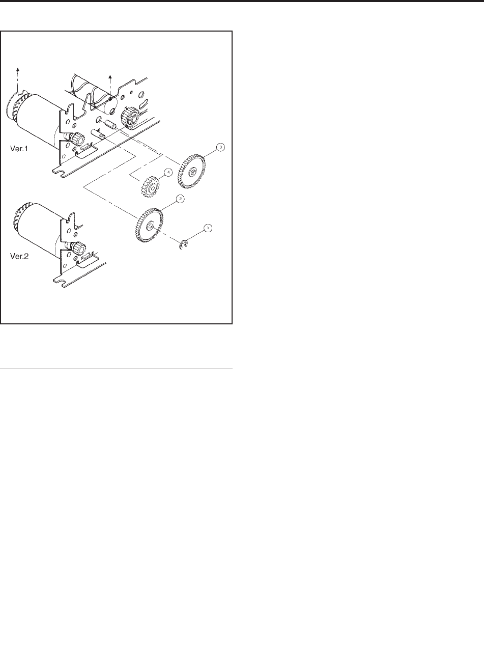
4.13 Gears
1. Remove
• Upper case unit according to the procedure de-
scribed in Section 4.1.
• Stop ring SE4 1
• Gear 2
• Gear 3
• Gear 4
2. Assembly (Ver.1)
Move the carriage to the left end. Align the gear
wheels so that the cut-out section of the drive shaft
and one end of the cut-out section of the timing pulse
plate are facing upward as shown in the figure.
Secure the gears with the stop rings.
3. Adjust
• Column displacement
(Refer to Section 3.4.)