


PARTS REPLACEMENT
4-5
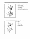
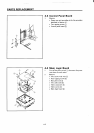
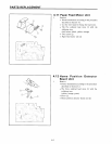
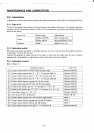
4.9 Terminal Board Unit
1. Remove
• Printer mechanism according to the procedure
described in Section 4.2.
• The ten soldered lead wires 1 with the soldering
iron.
• Two screws 2
• Terminal board unit 3
2. Adjust
• Column displacement
(Refer to Section 3.4.)
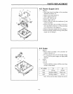
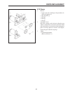
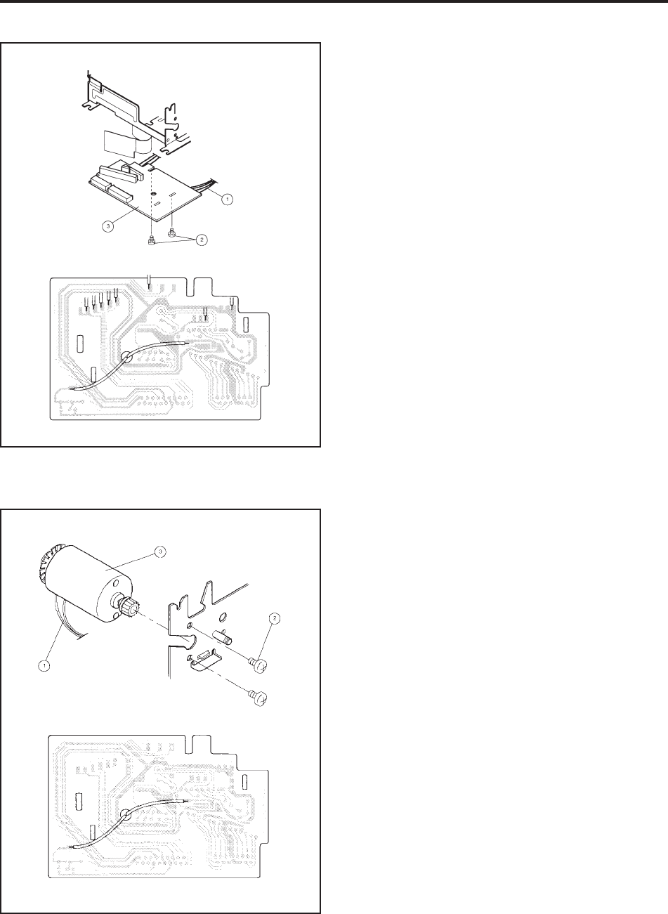
4.10 Carriage Motor Unit
1. Remove
• Printer mechanism according to the procedure
described in Section 4.2.
• The two soldered lead wires 1 with the soldering
iron. (black, red)
• Two screws 2
• Carriage motor unit 3
2. Adjust
• Printing speed (Refer to Section 3.3.)
• Column displacement (Refer to Section 3.4.)