


– 107 –
APPENDIX
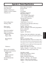
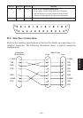
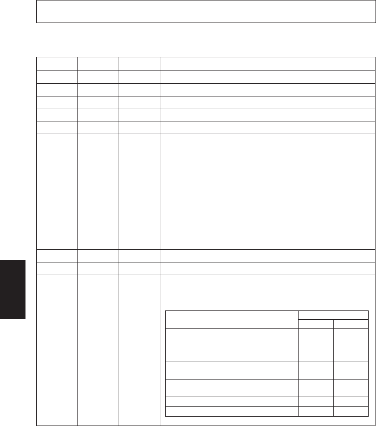
B-1. Pins and Signal Names
Pin No.
Signal Name
Direction Function
1FG— Frame ground
2 TXD OUT Transmission data
3 RXD IN Receive data
4 RTS OUT Always space
5 N.C. Not connected
6 DSR IN STAR Mode
Status of this signal is not checked.
ESC/POS Mode
In DTR/DSR communication mode when Memory Switch4-5 = 0,
indicates whether data receive from host is enabled or disabled.
Space: Receive enabled
Mark: Receive disabled
In DTR/DSR communication mode when Memory Switch 4-5=1,
status of this signal is not checked.
This signal is not checked in the X-ON/X-OFF communication
mode.
7 SG Signal ground
8 -19 N.C. Not connected
20 DTR OUT Indicates whether data receive from host is enabled or disabled.
DTR/DSR Communication Mode
Space when receive is enabled.
Appendix B: Serial Interface
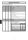
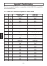
Printer status
Memory switch 6-9
01
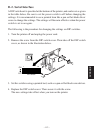
1. During the period from when the power is
turned on (including resetting using the in-
terface) to when the printer is ready to re-
ceive data.
2. During self printing and dot alignment ad-
justment.
3. When the printer stops printing due to a
paper end or a paper near end.
4. When an error has occurred.
5. When the receive buffer becomes full.
BUSY BUSY
BUSY BUSY
BUSY —
BUSY —
BUSY BUSY