


TABLE OF CONTENTS
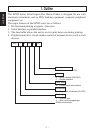
1. Outline ...............................................................................................................1
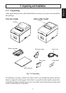
2. Unpacking and Installation ................................................................................2
2-1. Unpacking ..............................................................................................2
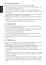
2-2. Locating the Printer ...............................................................................3
2-3. Handling Care ........................................................................................3
2-4. Maintenance ...........................................................................................3
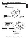
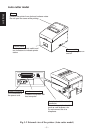
3. Parts Identification and Nomenclature ..............................................................4
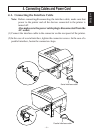
4. Connecting Cables and Power Cord ..................................................................6
4-1. Connecting the Interface Cable ..............................................................6
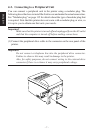
4-2. Connecting to a Peripheral Unit .............................................................7
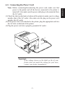
4-3. Connecting the Power Cord ...................................................................8
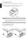
4-4. Turning Power On .................................................................................9
4-5. Attaching the Rear Cover.......................................................................9
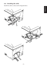
4-6. Installing the cable ...............................................................................10
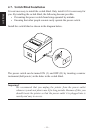
4-7. Switch Blind Installation .....................................................................11
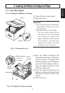
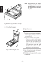
5. Loading the Ribbon Cartridge and Paper ........................................................12
5-1. Tear Bar Model ....................................................................................12
5-2. Auto Cutter Model ...............................................................................15
5-3. Installing the Roll Paper Guide ............................................................18
6. Control Panel and Other Functions .................................................................19
6-1. Control Panel .......................................................................................19
6-2. Basic Indicators ....................................................................................19
6-3. Errors ...................................................................................................20
6-4. Adjustment Mode ................................................................................22
Appendix A: General Specifications .................................................................104
Power Supply Specifications ......................................................................106
Appendix B: Serial Interface .............................................................................107
B-1. Pins and Signal Names ......................................................................107
B-2. Interface Connections ........................................................................108
Appendix C: Parallel Interface ..........................................................................109
C-1. Table of Connection Signals for Each Mode .....................................109
D-1. Parallel Interface ................................................................................111
Appendix D: DIP Switch Setting ......................................................................111
D-2. Serial Interface ...................................................................................112
Appendix E: Memory Switch Settings ..............................................................114
Appendix F: Peripheral Unit Driver Circuit .....................................................115
Appendix G: Adjusting the Dot Alignment Mode ...........................................117
Appendix H: Black Mark Sensor Alignment Mode .........................................119