


8 Sun SNMP Management Agent Addendum for the Netra 440 Server • April 2004
HDD2 Service Required Indicator
†
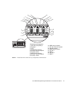
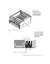
Hard Disk Drive 2 (2nd from right - viewed from front) FIGURE 2 – item 15
➥ Hard Disk Drive 3 Bay (right - viewed from front) FIGURE 2 – item 17
➥ HDD3 Okay To Remove Indicator FIGURE 2 – item 13
HDD3 Service Required Indicator
†
Hard Disk Drive 3 (right1 - viewed from front) FIGURE 2 – item 17
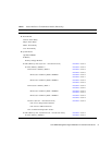
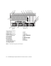
➥ Power Supply 0 Bay (right - viewed from rear) FIGURE 3 – item 15
➥ Power Supply 0 FIGURE 3 – item 15
➥ PS 0 Okay-To-Remove Indicator FIGURE 3 – item 15 and item 14
PS 0 Active Indicator
FIGURE 3 – item 15 and item 12
PS 0 Service-Required Indicator
FIGURE 3 – item 15 and item 13
PS 0 Over-Current Fault Monitor
PS 0 Fan Under-Speed Fault Monitor
PS 0 Over-Voltage Fault Monitor
PS 0 Under-Voltage Fault Monitor
PS 0 Power Inlet Presence Monitor
PS 0 Over-Temperature Fault Monitor
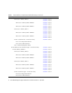
➥ Power Supply 1 Bay (2nd from right - viewed from rear) FIGURE 3 – item 16
➥ Power Supply 1 FIGURE 3 – item 16
➥ PS 1 Okay-To-Remove Indicator FIGURE 3 – item 16 and item 14
PS 1 Active Indicator
FIGURE 3 – item 16 and item 12
PS 1 Service-Required Indicator
FIGURE 3 – item 16 and item 13
PS 1 Over-Current Fault Monitor
PS 1 Fan Under-Speed Fault Monitor
PS 1 Over-Voltage Fault Monitor
PS 1 Under-Voltage Fault Monitor
PS 1 Power Inlet Presence Monitor
PS 1 Over-Temperature Fault Monitor
➥ Power Supply 2 Bay (2nd from left - viewed from rear) FIGURE 3 – item 20
➥ Power Supply 2 FIGURE 3 – item 20
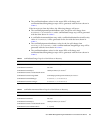
TABLE 1 Netra 440 Server Containment Model (Hierarchy) (Continued)
Model Description For Location, See: