


Sun SNMP Management Agent Addendum for the Netra 440 Server 9
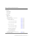
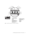
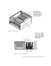
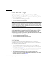
➥ PS 2 Okay-To-Remove Indicator FIGURE 3 – item 20 and item 14
PS 2 Active Indicator
FIGURE 3 – item 20 and item 12
PS 2 Service-Required Indicator
FIGURE 3 – item 20 and item 13
PS 2 Over-Current Fault Monitor
PS 2 Fan Under-Speed Fault Monitor
PS 2 Over-Voltage Fault Monitor
PS 2 Under-Voltage Fault Monitor
PS 2 Power Inlet Presence Monitor
PS 2 Over-Temperature Fault Monitor
➥ Power Supply 3 Bay (left - viewed from rear) FIGURE 3 – item 23
➥ Power Supply 3 FIGURE 3 – item 23
➥ PS 3 Okay-To-Remove Indicator FIGURE 3 – item 23 and item 14
PS 3 Active Indicator
FIGURE 3 – item 23 and item 12
PS 3 Service-Required Indicator
FIGURE 3 – item 23 and item 13
PS 3 Over-Current Fault Monitor
PS 3 Fan Under-Speed Fault Monitor
PS 3 Over-Voltage Fault Monitor
PS 3 Under-Voltage Fault Monitor
PS 3 Power Inlet Presence Monitor
PS 3 Over-Temperature Fault Monitor
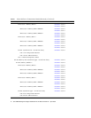
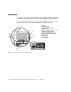
➥ System Configuration Card Reader FIGURE 1 – item 4
➥ System Configuration Card FIGURE 1 – item 4
➥ DVD Drive Bay FIGURE 1 – item 6
➥ DVD Drive FIGURE 1 – item 6
➥ Power Distribution Module Bay FIGURE 1 – item 7
➥ Power Distribution Module FIGURE 1 – item 7
Ethernet Port 0 (left - viewed from rear)
FIGURE 3 – item 19
Ethernet Port 1 (right - viewed from rear)
FIGURE 3 – item 18
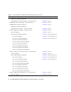
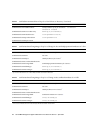
* TheSNMP modelmayshowfrequencyvaluesforslots1-4thataredifferent fromthoseshowninthistable;ifthatisthecase,ignore
the frequencyvalues shownin the SNMPmodel, anduse thefrequency valuesshown in thistable andthe regularNetra 440server
labels and documents instead. Refer to the Netra 440 Server Release Notes for more information.
† While the service-required indicator is represented in the containment model, it is not supported.
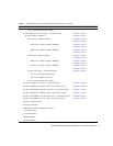
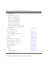
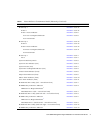
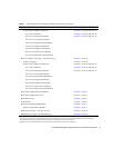
TABLE 1
Netra 440 Server Containment Model (Hierarchy) (Continued)
Model Description For Location, See: