4 Sun SNMP Management Agent Addendum for the Netra 440 Server • April 2004
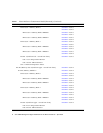
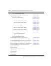
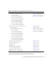
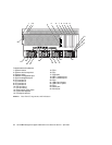
➥ Processor 1 Memory Bank 0 FIGURE 4 – item 3
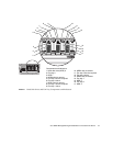
FIGURE 5 – item 5
➥ Processor 1 Memory Bank 0 DIMM 0 FIGURE 4 – item 3
FIGURE 5 – item 1
➥ Processor 1 Memory Bank 0 DIMM 1 FIGURE 4 – item 3
FIGURE 5 – item 2
➥ Processor 1 Memory Bank 1 FIGURE 4 – item 3
FIGURE 5 – item 6
➥ Processor 1 Memory Bank 1 DIMM 0 FIGURE 4 – item 3
FIGURE 5 – item 3
➥ Processor 1 Memory Bank 1 DIMM 1 FIGURE 4 – item 3
FIGURE 5 – item 4
➥ CPU 1 (2nd from left - viewed from front) FIGURE 4 – item 3
CPU 1 Core Temperature Monitor
CPU 1 Power OK Fault Sensor
CPU 1 Ambient Temperature Sensor
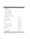
➥ CPU/Memory Slot 2 (2nd from right - viewed from front) FIGURE 4 – item 4
➥ CPU/Memory Module 2 FIGURE 4 – item 4
➥ Processor 2 Memory Bank 0 FIGURE 4 – item 4
FIGURE 5 – item 5
➥ Processor 2 Memory Bank 0 DIMM 0 FIGURE 4 – item 4
FIGURE 5 – item 1
➥ Processor 2 Memory Bank 0 DIMM 1 FIGURE 4 – item 4
FIGURE 5 – item 2
➥ Processor 2 Memory Bank 1 FIGURE 4 – item 4
FIGURE 5 – item 6
➥ Processor 2 Memory Bank 1 DIMM 0 FIGURE 4 – item 4
FIGURE 5 – item 3
➥ Processor 2 Memory Bank 1 DIMM 1 FIGURE 4 – item 4
FIGURE 5 – item 4
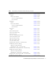
➥ CPU 2 (2nd from right - viewed from front) FIGURE 4 – item 4
CPU 2 Core Temperature Monitor
CPU 2 Power OK Fault Sensor
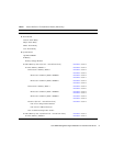
TABLE 1 Netra 440 Server Containment Model (Hierarchy) (Continued)
Model Description For Location, See:


