


Chapter 5: Advanced Motherboard Setup
5-3
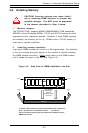
5-3 Connecting Cables
Now that the motherboard is installed, the next step is to connect the cables
to the board. These include the data (ribbon) cables for the peripherals and
control panel and the power cables.
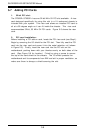
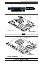
Connecting Data Cables
The ribbon cables used to transfer data from the peripheral devices
have been carefully routed to prevent them from blocking the flow of
cooling air that moves through the system from front to back. If you
need to disconnect any of these cables, you should take care to
keep them routed as they were originally after reconnecting them
(make sure the red wires connect to the pin 1 locations). The
following data cables (with their locations noted) should be con-
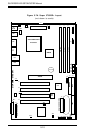
nected. (See the layout on page 5-10 for connector locations.)
l IDE Device Cables (J18 and J19)
l Floppy Drive Cable (J26)
l SCSI Device Cables (JPA1, JPA2, JPA3) (5010H only)
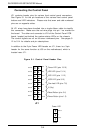
l Control Panel Cable (JF1, see next page)
Connecting Power Cables
The 370SSR+/370SSE+ has a 20-pin primary power supply connector
designated "ATX Power" for connection to the ATX power supply.
See Section 5-8 for power connector pin definitions.