


Chapter 5: Advanced Motherboard Setup
5-5
5-5 Installing Processors
Avoid placing direct pressure to the top of the pro
cessor package. Always connect the power cord last
and always remove it before adding, removing or
changing any hardware components.
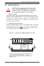
1. Installing the FCPGA processors:
The 370SSR+ /370SSE+has one 370-pin socket, which support Intel
Pentium III FCPGA and Celeron FCPGA/PPGA processors. Lift the lever on
the FCPGA socket and insert the processor (with the heat sink attached)
keeping the notched corner oriented toward pin one on the socket. Make
sure the processor is fully seated in the socket and and then close the
lever.(See Figure 5-4 for views of a 370-pin FCPGA socket before and
after processor installation.)
!
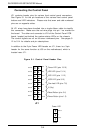
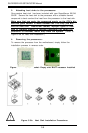
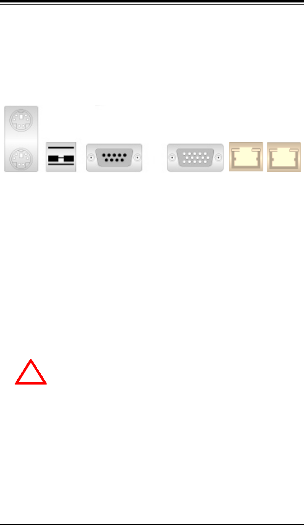
5-4 I/O Ports
The I/O ports are color coded in conformance with the PC 99 specification.
See Figure 5-2 below for the colors and locations of the various I/O ports.
Keyboard
(Purple)
Mouse
(Green)
USB
Ports
(Black)
VGA Graphics
Port (Blue)
COM1 Port
(Turquoise)
LAN1
Figure 5-2. I/O Ports
Note: The COM2 Port is a header on the motherboard, located behind the
mouse/keyboard ports.
LAN2