


Chapter 3: System Interface
3-3
l Power:
Indicates power is being supplied to the system's power
supply units. This LED should normally be illuminated when the system is
operating.
3-4 SCSI Drive Carrier LEDs (5010H only)
Each SCSI drive carrier has two LEDs.
l Green: When illuminated, the green LED on the front of the SCSI drive
carrier indicates drive activity. A connection to the SCSI SCA backplane
enables this LED to blink on and off when that particular drive is being
accessed.
l Red: A SAF-TE compliant backplane is needed to activate the red
LED to indicate a drive failure. (A SAF-TE compliant SCSI backplane is
optional on the 5010H/5010E.) If one of the SCSI drives fail, you should be
notified by your system management software. Please refer to Section 6-
4 for instructions on replacing failed SCSI drives.
3-5 Power Supply Switch
An on/off switch is located on the back of the power supply. This switch
should normally be on at all times. Turning this switch to the off position
removes both the main and standby power from the system, as opposed to
the power button located on the control panel on the front of the chassis.
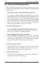
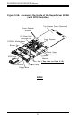
3-6 Motherboard LEDs
l
PW (Power_On) LEDPW (Power_On) LED
PW (Power_On) LEDPW (Power_On) LED
PW (Power_On) LED
There is one PW (Power_on) LED on the motherboard. When illuminated, it
indicates that system power is present on the motherboard. This LED is
located in the corner of the 370SSR+/370SSE+ near the DIMM2 slot.