


Chapter 5: Advanced Motherboard Setup
5-17
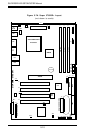
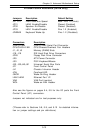
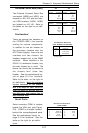
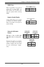
Serial Ports
Serial connector COM1 is located
beside the VGA port (see Figure
5-8). COM2 is a header located
behind the mouse/keyboard ports.
See the motherboard layout on
page 5-10 for locations. See the
table on the right for pin defini-
tions.
Serial Port Pin Definitions
(COM1, COM2)
Pin Number Definition
1 DCD
2 Serial In
3 Serial Out
4 DTR
5 Ground
Pin Number Definition
6 DSR
7 RTS
8 CTS
9 RI
10 NC
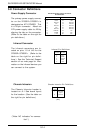
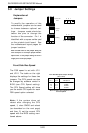
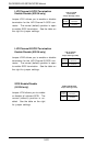
Fan Header Pin Definitions
(CPU, CHASSIS and OH FANs)
Pin
Number
1
2
3
Definition
Ground (black)
+12V (red)
Tachometer
* Caution: These fan headers
are DC power.
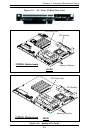
Fan Headers*
There are several fan headers on
the 370SSR+/SSE+ that provide
cooling for various components.
In addition to one fan header for
the processor (located near the
ATX Power Supply), there are one
overheat and two chassis fan
headers located next to the DIMM
modules. When installed in the
SC810 1U rackmount chassis, only
the main blower fan is used. The
blower fan should be connected to
the chassis fan2 (blow fan)
header. See the motherboard lay-
out on page 5-10 for locations.
Refer to the table on the right for
pin definitions. Note: The maximum
current limitation for the onboard
fans is 0.6 amps for each, not to ex-
ceed 1.25 amps for any two fans. I.e.
both CPU fans, both chassis fans or
both overheat fans.
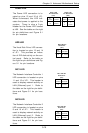
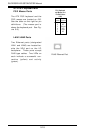
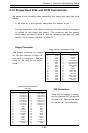
Universal Serial Bus (USB)
Two External Universal Serial Bus
connectors (USB0 and USB1) are
located on J32, J33, and two Inter-
nal USB headers (USB2, USB3)
are located on J43, J51. Refer to
the tables on the right for pin defi-
nitions.
Universal Serial Bus Pin Definitions
Pin
Number Definition
1 +5V
2 P0-
3 P0+
4 Ground
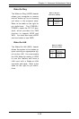
Pin
Number Definition
1 +5V
2P0-
3 P0+
4 Ground
J32
J33
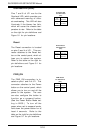
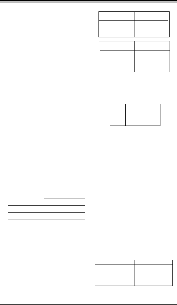
Pin
Number Definition
1 +5V
2 P0-
3 P0+
4 Ground
5 key
Pin
Number Definition
1 +5V
2P0-
3 P0+
4 Ground
5 Ground
J43
J51