


Chapter 5: Advanced Motherboard Setup
5-23
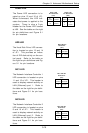
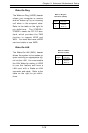
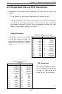
IDE Connectors
There are no jumpers to config-
ure the onboard IDE connectors
J18 and J19. Refer to the table
on the left for pin definitions.
Pin Number Function
1 Reset IDE
3 Host Data 7
5 Host Data 6
7 Host Data 5
9 Host Data 4
11 Host Data 3
13 Host Data 2
15 Host Data 1
17 Host Data 0
19 GND
21 DRQ3
23 I/O Write-
25 I/O Read-
27 IOCHRDY
29 DACK3-
31 IRQ14
33 Addr 1
35 Addr 0
37 Chip Select 0
39 Activity
Pin Number Function
2 GND
4 Host Data 8
6 Host Data 9
8 Host Data 10
10 Host Data 11
12 Host Data 12
14 Host Data 13
16 Host Data 14
18 Host Data 15
20 Key
22 GND
24 GND
26 GND
28 BALE
30 GND
32 IOCS16-
34 GND
36 Addr 2
38 Chip Select 1-
40 GND
IDE Connector Pin Definitions
(J18, J19)
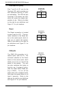
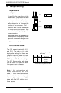
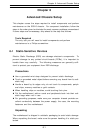
Floppy Connector
The floppy connector is located
on J26 and requires a 34-pin rib-
bon cable for operation. See the
table on the right for pin defini-
tions.
Pin Number Function
1 GND
3 GND
5 Key
7 GND
9 GND
11 GND
13 GND
15 GND
17 GND
19 GND
21 GND
23 GND
25 GND
27 GND
29 GND
31 GND
33 GND
Pin Number Function
2 FDHDIN
4 Reserved
6 FDEDIN
8 Index-
10 Motor Enable
12 Drive Select B-
14 Drive Select A-
16 Motor Enable
18 DIR-
20 STEP-
22 Write Data-
24 Write Gate-
26 Track 00-
28 Write Protect-
30 Read Data-
32 Side 1 Select-
34 Diskette
Floppy Connector Pin Definitions (J26)
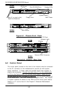
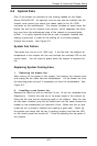
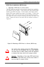
5-10 Floppy/Hard Disk and SCSI Connections
Be aware of the following when connecting the floppy and hard disk drive
cables:
• A red mark on a wire typically designates the location of pin 1.
• A single floppy disk drive ribbon cable has 34 wires and two connectors
to provide for two floppy disk drives. The connector with the twisted
wires always connects to drive A, and the connector that does not have
twisted wires always connects to drive B.