


5-16
SUPERSERVER 5010H/5010E Manual
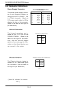
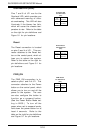
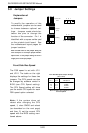
Reset
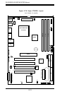
The Reset connection is located
on pins 3 and 4 of JF1. This con-
nector attaches to the Reset but-
ton on the control panel, which al-
lows you to reboot the system.
Refer to the table on the right for
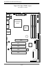
pin definitions and Figure 5-1 for
pin locations.
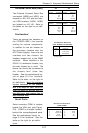
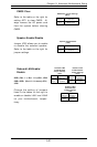
PWR_ON
The PWR_ON connection is lo-
cated on pins 1 and 2 of JF1. This
connector attaches to the Power
button on the control panel, which
allows you to turn on and off the
power to the system. The user
can also configure this button to
function as a suspend button.
(See the Power Button Mode set-
ting in BIOS.) To turn off the
power when set to suspend mode,
hold down the power button for at
least 4 seconds. Refer to the
table on the right for pin definitions
and Figure 5-1 for pin locations.
Pin
Number
1
2
Definition
PW_ON
Power
PWR Button
Pin Definitions
(JF1)
Reset Button
Pin Definitions
(JF1)
Pin
Number
3
4
Definition
Reset
Ground
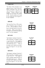
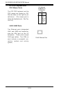
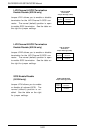
Overheat LED (JOH)
Pins 7 and 8 of JF1 are for the
Overheat LED, which provides you
with advanced warning of chas-
sis overheating. This LED will also
illuminate if the blower fan fails,
which will cause the chassis tem-
perature to rise. Refer to the table
on the right for pin definitions and
Figure 5-1 for pin locations.
Overheat LED
Pin Definitions
(JF1)
Pin
Number
7
8
Definition
Power
Control