


Chapter 5: Advanced Serverboard Setup
5-23
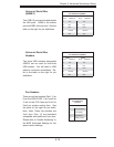
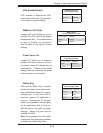
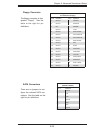
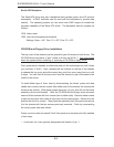
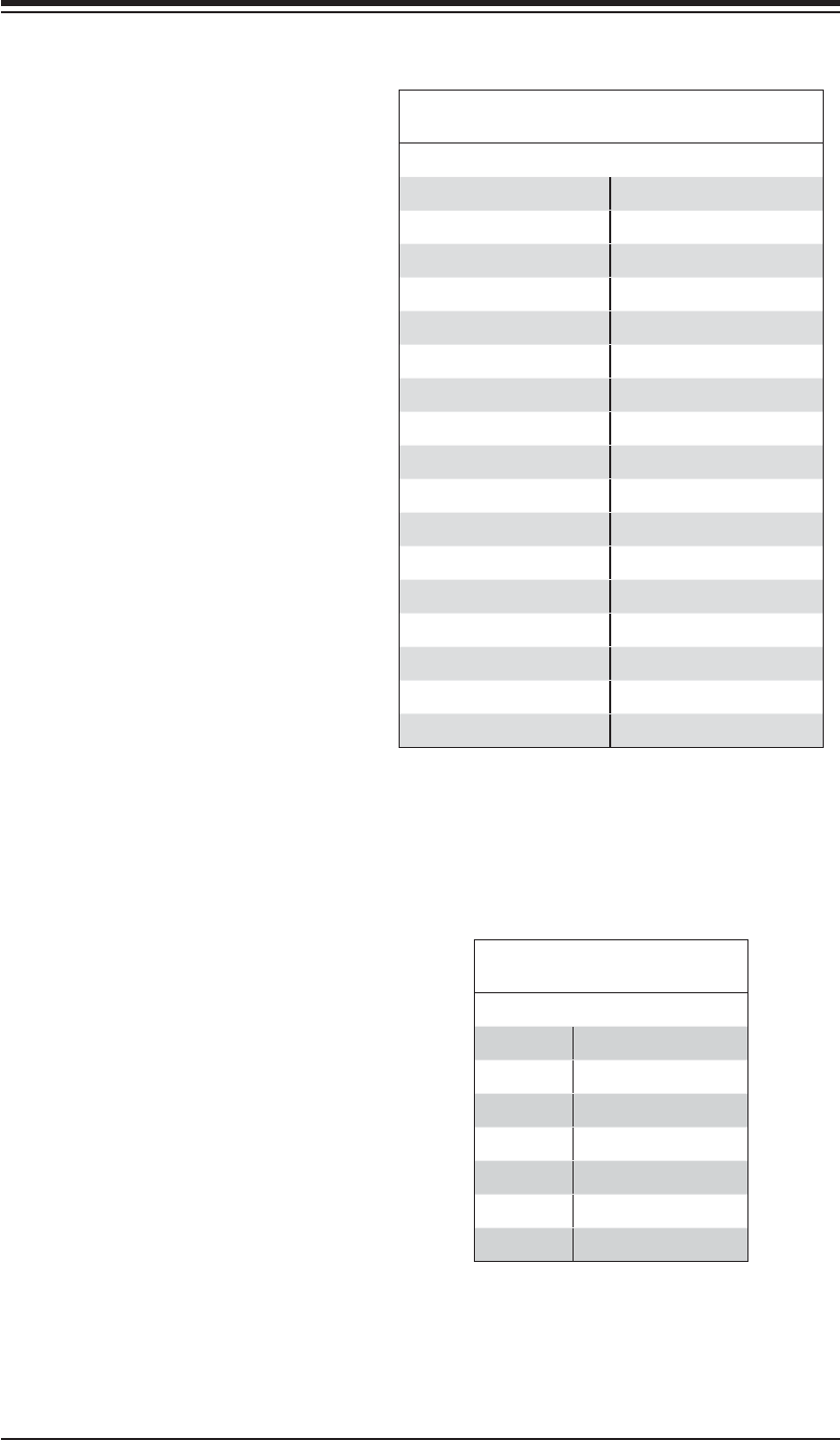
Floppy Connector
The fl oppy connector is des-
ignated "Floppy". See the
table to the right for pin
defi nitions.
Floppy Drive Connector
Pin Defi nitions (Floppy)
Pin# Defi nition Pin # Defi nition
1 Ground 2 FDHDIN
3 Ground 4 Reserved
5 Key 6 FDEDIN
7 Ground 8 Index
9 Ground 10 Motor Enable
11 Ground 12 Drive Select B
13 Ground 14 Drive Select B
15 Ground 16 Motor Enable
17 Ground 18 DIR
19 Ground 20 STEP
21 Ground 22 Write Data
23 Ground 24 Write Gate
25 Ground 26 Track 00
27 Ground 28 Write Protect
29 Ground 30 Read Data
31 Ground 32 Side 1 Select
33 Ground 34 Diskette
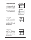
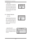
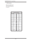
SATA Connectors
There are no jumpers to con-
fi gure the onboard SATA con-
nectors. See the table on the
right for pin defi nitions.
SATA Connector Pin Defi nitions
(I-SATA0, I-SATA1)
Pin # Defi nition
1 Ground
2TXP
3TXN
4 Ground
5RXN
6RXP
7 Ground