


6-2
S
UPERSERVER 6014L-T User's Manual
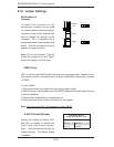
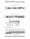
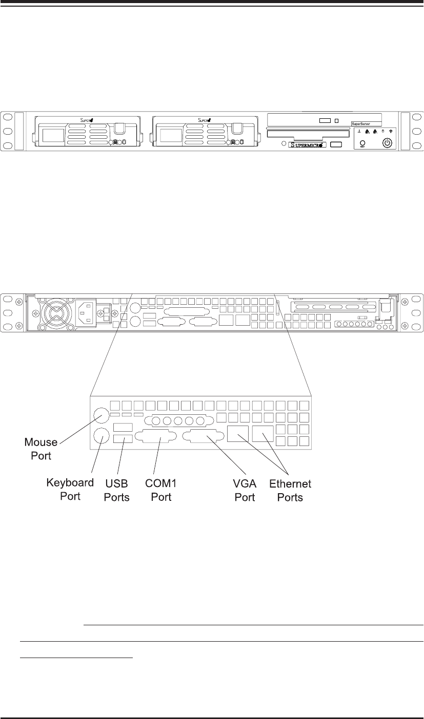
Figure 6-2. Chassis Rear View
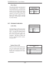
6-2 Control Panel
The control panel (located on the front of the chassis) must be connected to the JF1
connector on the serverboard to provide you with system control buttons and status
indicators. These wires have been bundled together in a ribbon cable to simplify the
connection. Connect the cable from JF1 on the serverboard to the correct neader
on the Control Panel PCB (printed circuit board). Make sure the red wire plugs into
pin 1 on both headers. Pull all excess cabling out of the airfl ow path. The LEDs
inform you of system status. See Chapter 3 for details on the LEDs and the control
panel buttons. Details on JF1 can be found in Chapter 5.
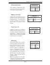
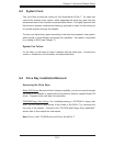
Figure 6-1. Chassis Front View