


Chapter 5: Advanced Serverboard Setup
5-11
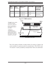
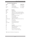
Serverboard Quick Reference
Jumper Description Default Setting
JBT1 CMOS Clear (See Section 5-8)
JPG1 VGA Enable/Disable Pins 1-2 (Enabled)
JPL1/JPL2 LAN1/2 Enable/Disable Pins 1-2 (Enabled)
JWD1 Watch Dog Enable/Disable/Reset Pins 1-2 (Reset)
Connector Description
COM1 COM1 Serial Port
FAN 1 Cooling Fan Header
Infi niBand Infi niBand Connector (X8DTT-HIBX/HIBXF/HIBQ/HIBQF)
IPMB IPMB Header (for an IPMI Card) (X8DTT-HF/-HIBXF/-HIBQF)
JF2 SMC Proprietary Slot for Power, FP Control & I-SATA
Connections
JNMI1 NMI (Non-Maskable Interrupt) Header
JRST1 System Reset Header
JSPK1 Internal Speaker/Buzzer Header
LAN1/2 Gigabit Ethernet (RJ45) Ports
LAN (IPMI dedicated) LAN (RJ45) Port for IPMI 2.0 (X8DTT-HIBXF+/-HIBQF+ only
Slot 1 PCI-E 2.0 x16 slot
SW1 Unit Identifi er Switch
USB 0/1 Universal Serial Bus (USB) Ports 0/1
USB 2/3 (JUSB2) Front Accessible USB connections
VGA Video Port
LED Description
LE1 Onboard Standby PWR warning LED Indicator
LE2 BMC Heartbeat LED Indicator
LE3 HDD/SATA LED Indicator
LE4 (Rear) Unit Identifi er (UID) LED Indicator
LEB1 Infi niBand Link LED (X8DTT-HIBXF+/HIBQF+)
Note: Jumpers not indicated are for test purposes only.