


Chapter 5: Advanced Serverboard Setup
5-13
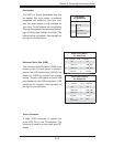
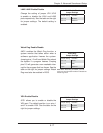
Fan Header
Pin Defi nitions
Pin# Defi nition
1 Ground
2 +12V
3 Tachometer
4 PWR Modulation
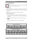
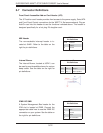
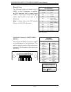
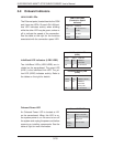
Universal Serial Bus (USB)
Two Universal Serial Bus ports (USB0/1) are
located on the I/O back panel. In addition,
another two USB connections (USB2/3) are
located at JUSB2 to provide front chassis
access. Connect USB cables to these USB
ports/headers to use USB connections. (USB
cables are not included). See the tables on
the right for pin defi nitions.
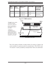
Fan Header
The X8DTT-H Series serverboard has one
fan header. This 4-pin header is backward
compatible with traditional 3-pin fans, how-
ever, fan speed control is only available for
4-pin fans. The fan speeds are controlled by
Thermal Management via Hardware Monitor-
ing in the Advanced Setting in the BIOS. (The
default setting is disabled.) See the table on
the right for pin defi nitions.
Back Panel USB0/1
Pin Defi nitions
Pin# Defi nition Pin# Defi nition
1 +5V 5 +5V
2 USB_PN1 6 USB_PN0
3 USB_PP1 7 USB_PP0
4 Ground 8 Ground
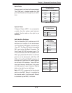
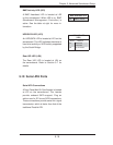
Front Panel USB2/3
Pin Defi nitions
USB 2
Pin # Defi nition
USB 3
Pin # Defi nition
1 +5V 6 +5V
2 USB_PN2 7 USB_PN3
3 USB_PP2 8 USB_PP3
4 Ground 9 Ground
5 No
Connection
10 Key
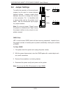
Video Connector
A Video (VGA) connector is located next
to the COM Port on the IO backplane. This
connector is used to provide video and CRT
display.