


5-14
SUPERSERVER 6026TT-GTRF/GIBXRF/GIBQRF User's Manual
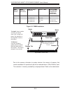
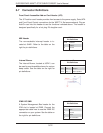
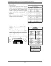
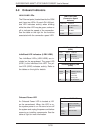
Ethernet Ports
Two Ethernet ports are located next to
USB0/1 on the IO backplane. In addition,
an IPMI Dedicated LAN is located above
USB0/1. These ports accept RJ45 type
cables. See the table on the right for pin
defi nitions.
Note 1: Please refer to the LED Indicator
Section for LAN LED information.
LAN Ports
Pin Defi nitions
Pin# Defi nition Pin# Defi nition
1 P2V5SB 10 SGND
2 TD0+ 11 Act LED
3 TD0- 12 P3V3SB
4 TD1+ 13 Link 100 LED
(Yellow, +3V3SB)
5 TD1- 14 Link 1000 LED
(Yellow, +3V3SB)
6 TD2+ 15 Ground
7 TD2- 16 Ground
8 TD3+ 17 Ground
9 TD3- 88 Ground
(NC: No Connection)
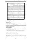
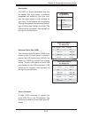
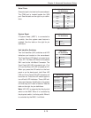
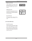
Infi niBand Connection (X8DTT-HIBXF+/
HIBQF+)
The onboard Infi niBand connector is located
on the backplane on the serverboard. This
switch is primarily used for High-performance
computing. See the table on the right for pin
defi nitions.
Infi niBand
Pin Defi nitions
Pin # Defi nition Pin # Defi nition
S1 Input
Pair0:Pos
S9 Output
Pair3:Pos
S2 Input
Pair0:Neg
S10 Output
Pair3:Neg
S3 Input
Pair1:Pos
S11 Output
Pair2:Pos
S4 Input
Pair1:Neg
S12 Output
Pair2:Neg
S5 Input
Pair2:Pos
S13 Output
Pair1:Pos
S6 Input
Pair2:Neg
S14 Output
Pair1:Neg
S7 Input
Pair3:Pos
S15 Output
Pair0:Pos
S8 Input
Pair3:Neg
S16 Output
Pair0:Neg
G1
G2
G3
G4
G5
G6
G7
G8
G9
S1
S2
S3
S4
S5
S6
S7
S8
S9
S10
S11
S12
S13
S14
S15
S16
Infi niBand Ground Pins
(G1~G9) Pin Defi nitions
Pin# Defi nitions
G1~G9 Ground