


2-20
C2SBA+II/C2SBA+/C2SBA/C2SBE User's Manual
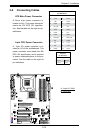
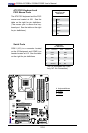
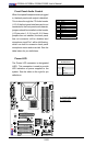
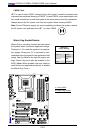
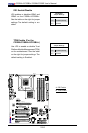
Front Panel Audio Control
When front panel headphones are plugged
in, the back panel audio output is disabled.
This is done through the FP Audio header
(J12). If the front panel interface card is not
connected to the front panel audio header,
jumpers should be installed on the header
(J12) pin pairs: 1-2, 5-6, and 9-10. If these
jumpers are not installed, the back panel
line out connector will be disabled and
microphone input Pin 1 will be left oating,
which can lead to excessive back panel
microphone noise and cross talk. See the
table below for pin denitions.
High Definition Front Panel Audio
Pins# Signal
0,&B/
$8'B*1'
0,&B5
)3B$XGLR'HWHFW
/LQHBB5
3XOOGRZQWR*URXQG
)3B-DFN'HWHFW
.H\
/LQHBB/
3XOOGRZQWR*URXQG
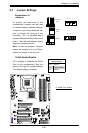
FAN2
FAN3
FAN1
JI2C1
JI2C2
JWOR
FAN4
JP3
JWD
JLED
Battery
DIMM1A
DIMM2A
DIMM1B
DIMM2B
I-SATA4
I-SATA5
WO
Speaker
COM1
KB/MOUSE
CPU Fan
VGA
USB
3/4/5/6
USB 1/2
LAN
Fan5
Audio
4-Pin PWR
Processor
Slot7 PCI-E x1
Slot6 PCI-E x16
Slot5 PCI-E x4
Slot4 PCI-33MHz
JP5
Slot3 PCI-33MHz
JP2
Slot2 PCI-33MHz
Buzzer
SPKR1
Slot1 PCI-33MHz
C2SBA
WOL
IDE#2
IDE#1
FP USB 7/8
FP USB 9/10
I-SATA0
I-SATA1
JL1
LE1
Front Panel CTRL
Intel G33
North Bridge
South Bridge
Intel ICH9(R)
24-pin ATX PWR
Audio CTRL
CD-IN
COM2
Front Audio
W83627DHG
Floppy
S I/O
IDE CTRL
ITE 8212
Audio Enabled
Front-Access USB 11Front-Access USB 12
I-SATA2
I-SATA3
JPUSB1
JKB
JPUSB2
GLAN CTRL
JPL1
JBT1
BIOS
Parallel Port
A
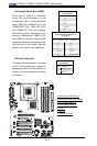
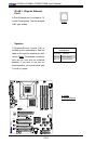
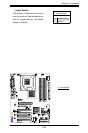
A. Front Panel Audio
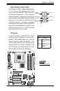
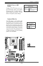
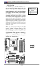
B. PWR LED
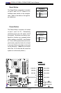
Power LED
The Power LED connector is designated
JLED. This connection is used to provide
LED Indication of power supplied to the
system. See the table on the right for pin
denitions.
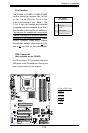
PWR LED
PinDenitions
Pin# Denition
1 +5V
2 Key
3 Ground
B