


SBA-7142G-T4 Blade Module User’s Manual
5-6
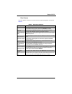
IDE Configuration
The menu options in the IDE ConfiguraTION submenu and their descriptions are shown
in Table 5-4
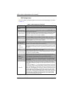
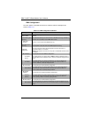
Table 5-4. IDE Configuration Submenu
Menu Option Description
OnChip SATA
Channel
This option enables or disables the on-chip SATA channel.
OnChip SATA Type
This option specifies the on-chip SATA type. Options include Native IDE, RAID,
AMD_AHCI and Legacy IDE.
RAID Codebase
This submenu appears when you choose "RAID" from the "OnChip SATA Type"
setting above. This setting allows you to select the codebase for using your
RAID setup. Options are either Adaptec or DotHill.
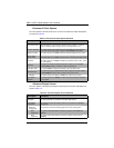
SATA IDE Combined
Mode
This option enables or disables SATA IDE Combined Mode in your system.
PATA Channel Config
This option specifies the PATA Channel configuration. You may specify either
SATA as Primary or SATA as Secondary as options.
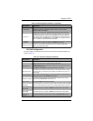
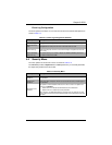
Primary/Secondary/
Third/Fourth Master/
Slave submenus
These submenus are specifying options for each installed Master/Slave drive in
the system. Their common options are described below.
Device
Information
Static device information is shown at the top of this submenu for Device, Vendor,
Size, LBA Mode, Block Mode, PIO Mode, Async DMA, Ultra DMA and S.M.A.R.T
information.
Type
Use thsi option to select the type of device connected to the system. Options
include Not Installed, Auto, CD/DVD and ARMD.
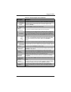
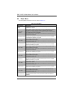
LBA/Large Mode
LBA (Logical Block Addressing) is a method of addressing data on a disk drive.
The options are Disabled and Auto.
Block
(Multi-Sector
Transfer)
Block mode boosts IDE drive performance by increasing the amount of data
transferred. Only 512 bytes of data can be transferred per interrupt if block mode
is not used. Block mode allows transfers of up to 64 KB per interrupt.
Select "Disabled" to allow the data to be transferred from and to the device one
sector at a time. Select "Auto" to allows the data transfer from and to the device
occur multiple sectors at a time if the device supports it. The options are Auto
and Disabled.
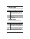
PIO Mode
PIO (Programmable I/O) mode programs timing cycles between the IDE drive
and the programmable IDE controller. As the PIO mode increases, the cycle time
decreases.
The options are Auto, 0, 1, 2, 3, and 4. Select Auto to allow BIOS to auto detect
the PIO mode. Use this value if the IDE disk drive support cannot be determined.
Select 0 to allow BIOS to use PIO mode 0, which has a data transfer rate of 3.3
MBs. Select 1 to allow BIOS to use PIO mode 1, which has a data transfer rate of
5.2 MBs. Select 2 to allow BIOS to use PIO mode 2, which has a data transfer
rate of 8.3 MBs. Select 3 to allow BIOS to use PIO mode 3, which has a data
transfer rate of 11.1 MBs. Select 4 to allow BIOS to use PIO mode 4, which has a
data transfer rate of 16.6 MBs. This setting generally works with all hard disk
drives manufactured after 1999. For other disk drives, such as IDE CD-ROM
drives, check the specifications of the drive.