


SBA-7142G-T4 Blade Module User’s Manual
A-8
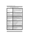
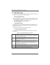
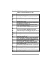
40h
Preparing the descriptor tables next.
42h
The descriptor tables are prepared. Entering protected mode for the
memory test next.
43h
Entered protected mode. Enabling interrupts for diagnostics mode next.
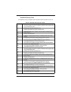
44h
Interrupts enabled if the diagnostics switch is on. Initializing data to check
memory wraparound at 0:0 next.
45h
Data initialized. Checking for memory wraparound at 0:0 and finding the
total system memory size next.
46h
The memory wraparound test is done. Memory size calculation has been
done. Writing patterns to test memory next.
47h
The memory pattern has been written to extended memory. Writing
patterns to the base 640 KB memory next.
48h
Patterns written in base memory. Determining the amount of memory
below 1 MB next.
49h
The amount of memory below 1 MB has been found and verified.
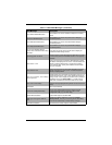
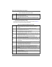
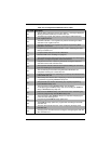
4Bh
The amount of memory above 1 MB has been found and verified.
Checking for a soft reset and clearing the memory below 1 MB for the soft
reset next. If this is a power on situation, going to checkpoint 4Eh next.
4Ch
The memory below 1 MB has been cleared via a soft reset. Clearing the
memory above 1 MB next.
4Dh
The memory above 1 MB has been cleared via a soft reset. Saving the
memory size next. Going to checkpoint 52h next.
4Eh
The memory test started, but not as the result of a soft reset. Displaying
the first 64 KB memory size next.
4Fh
The memory size display has started. The display is updated during the
memory test. Performing the sequential and random memory test next.
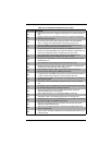
50h
The memory below 1 MB has been tested and initialized. Adjusting the
displayed memory size for relocation and shadowing next.
51h
The memory size display was adjusted for relocation and shadowing.
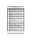
52h
The memory above 1 MB has been tested and initialized. Saving the
memory size information next.
53h
The memory size information and the CPU registers are saved. Entering
real mode next.
54h
Shutdown was successful. The CPU is in real mode. Disabling the Gate
A20 line, parity, and the NMI next.
57h
The A20 address line, parity, and the NMI are disabled. Adjusting the
memory size depending on relocation and shadowing next.
58h
The memory size was adjusted for relocation and shadowing. Clearing
the Hit <DEL> message next.
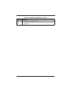
Table A-4. Uncompressed Initialization Error Codes
Post Code Description