


Chapter 2: Installation
2-3
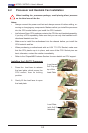
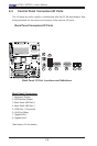
Socket Key
(Socket Notch)
South Center Edge
North Center Edge
Load Lever
CPU in the CPU socket
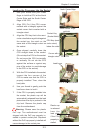
Plastic cap
is released
fro m the
load plate
if the CPU
properly in-
stalled.
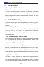
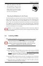
Use your thumb and your index 1.
nger to hold the CPU at the North
Center Edge and the South Center
Edge of the CPU.
Align CPU Pin1 (the CPU corner 2.
marked with a triangle) against the
socket corner that is marked with a
triangle cutout.
Align the CPU key that is the semi-3.
circle cutout below a gold dot against
the socket key, the notch on the
same side of the triangle cutout on
the socket.
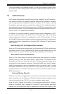
Once aligned, carefully lower the 4.
CPU straight down to the socket.
(Do not drop the CPU on the socket.
Do not move the CPU horizontally
or vertically. Do not rub the CPU
against the surface or against any
pins of the socket to avoid damage
to the CPU or the socket.)
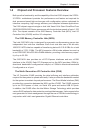
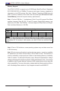
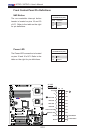
With the CPU installed in the socket, 5.
inspect the four corners of the
CPU to make sure that the CPU is
properly installed. Then, close the
load plate.
Use your thumb to gently push the 6.
load lever down to lock it.
If the CPU is properly installed into 7.
the socket, the plastic cap will be
automatically released from the load
plate when the clip is pushed in the
clip lock. Remove the plastic cap
from the motherboard.
Warning: Please save the plastic
PnP cap. The motherboard must be
shipped with the PnP cap properly in-
stalled to protect socket pins. Shipment
without the PnP cap properly installed will
cause damage to the socket pins.
!
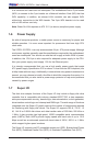
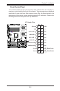
CPU Key (semi-
circle cutout)
below the circle.
CPU Pin1
Corner with a
triangle cutout
gold dot
Loading the Processor into the Socket