


Chapter 2: Installation
2-11
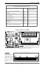
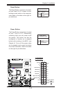
Power Button
OH/Fan Fail LED
1
NIC1 LED
Reset Button
2
HDD LED
Power LED
Reset
PWR
Vcc
Vcc
Vcc
Vcc
Ground
Ground
1920
Vcc
X
Ground
NMI
X
Vcc
PWR Fail LED
NIC2 LED
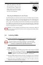
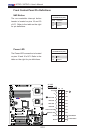
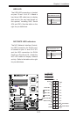
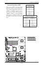
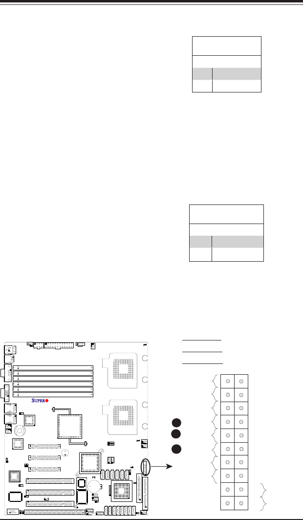
NIC1/NIC2 LED Indicators
The NIC (Network Interface Control-
ler) LED connection for GLAN port1
is located on pins 11 and 12 of JF1
and the LED connection for GLAN
Port2 is on Pins 9 and 10. Attach the
NIC LED cables to display network
activity. Refer to the table on the right
for pin denitions.
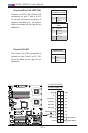
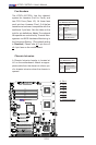
HDD LED
The HDD LED connection is located
on pins 13 and 14 of JF1. Attach a
hard drive LED cable here to display
disk activity (for any hard drives on
the system, including SAS, Serial
ATA and IDE). See the table on the
right for pin denitions.
HDD LED
PinDenitions(JF1)
Pin# Denition
13 +5V
14 HD Active
GLAN1/2 LED
PinDenitions(JF1)
Pin# Denition
9/11 Vcc
10/12 Ground
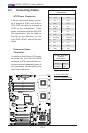
A
B
C
A. HDD LED
B. NIC1 LED
C. NIC2 LED
X7DCL-3/i