


Chapter 2: Installation
2-17
JBT1
DIMM2A
SP1
JI2C1
JI2C2
JL1
LED5
LED6
LED3
JWD1
JPG1
JPL2
JPA1
Fan 4
JD1
LED4
JWOL1
JPWF1
JAR
8-Pin PWR
I-Button
LAN
CTRL
VGA
CTRL
S I/O
SATA4
SATA3
SATA2
SATA1
SATA0
SATA5
SATA-GPIO0
Battery
SAS0
SAS1
SAS2
SAS3
SAS4
SAS5
SAS6
SAS7
PWR LED
JP1
JP2
COM2
JWOR1
JKEY1
Buzzer
BIOS
SATA-GPIO1
ITE
CTRL
LAN
CTRL
DIMM1A
DIMM2B
DIMM1B
DIMM2C
DIMM1C
LED1
SAS-GPIO0
SAS-GPIO1
24-Pin PWR
JPA2
System Status LED
Fan 1
CPU1 VRM OH LED
CPU2 VRM OH LED
Floppy
IDE
BPI
2
C
USB2/3
SMB_PS
KB/MS
COM1
VGA
FAN6
Slot4 PCI-E x4(in x8 slot)
Slot1 PCI 33MHz
SIMLC
USB0/1
LAN1
LAN2
FAN5
CPU1
CPU2
Fan 2
Fan 3
FP CTRL
USB4/5
Slot2 PCI 33MHz
Slot3 PCI 33MHz
Slot5 PCI-E x8
Slot6 PCI-E x8
Intel
5100
North Bridge
South Bridge
ICH9R
Intel
LSI
SAS
CTRL
JPL1
X7DCL-3/i
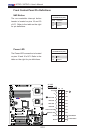
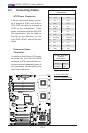
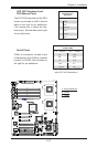
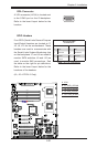
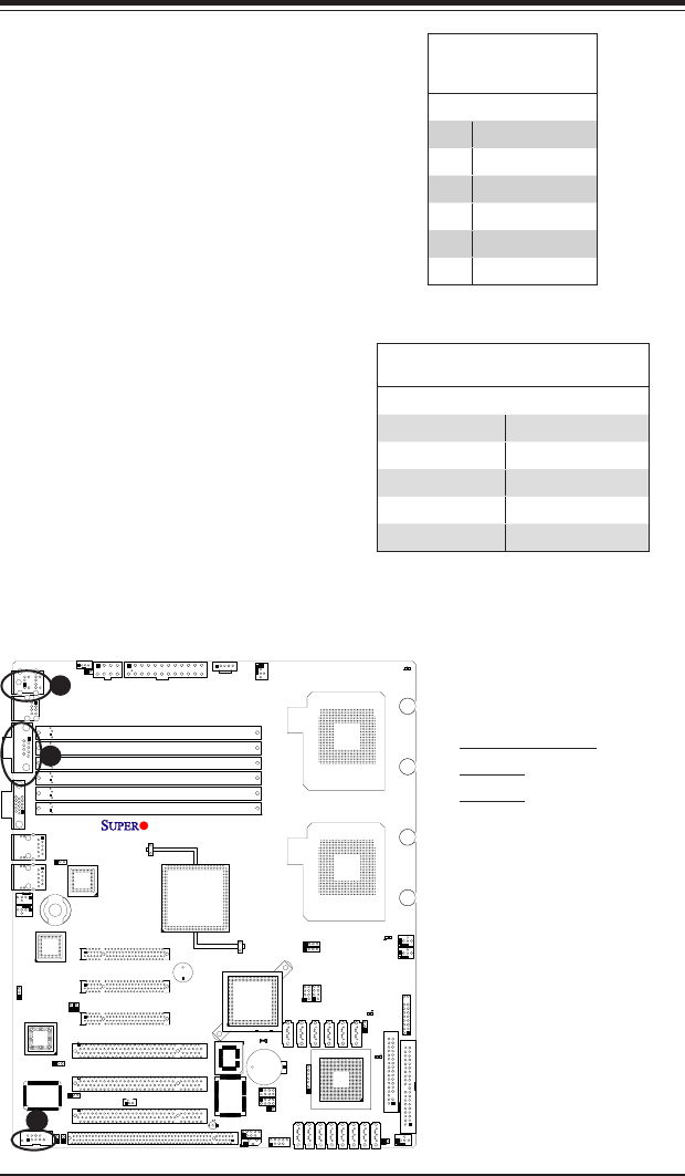
ATX PS/2 Keyboard and
PS/2 Mouse Ports
The ATX PS/2 keyboard and the PS/2
mouse are located at JKM1. See the
table on the right for pin denitions.
(The mouse port is above the key-
board port.) See the table on the right
for pin denitions.
PS/2 Keyboard and
Mouse Port Pin
Denitions
Pin# Denition
1 Data
2 NC
3 Ground
4 VCC
5 Clock
6 NC
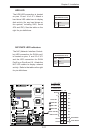
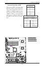
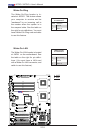
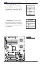
Serial Ports
COM1 is a connector located on the
IO Backpanel, and COM2 is a header
located at JCOM2. See the table on
the right for pin denitions.
SerialPortPinDenitions
(COM1/COM2)
Pin # Denition Pin # Denition
1 CD 6 DSR
2 RD 7 RTS
3 TD 8 CTS
4 DTR 9 RI
5 Ground 10 NC
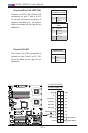
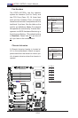
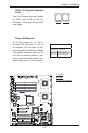
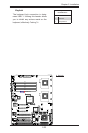
A
B
C
A. Keyboard/Mouse
B. COM1
C. COM2
(Pin 10 is available on COM2
only. NC: No Connection.)