


2-28
X7DCL-3/X7DCL-i User's Manual
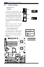
JBT1
DIMM2A
SP1
JI2C1
JI2C2
JL1
LED5
LED6
LED3
JWD1
JPG1
JPL2
JPA1
Fan 4
JD1
LED4
JWOL1
JPWF1
JAR
8-Pin PWR
I-Button
LAN
CTRL
VGA
CTRL
S I/O
SATA4
SATA3
SATA2
SATA1
SATA0
SATA5
SATA-GPIO0
Battery
SAS0
SAS1
SAS2
SAS3
SAS4
SAS5
SAS6
SAS7
PWR LED
JP1
JP2
COM2
JWOR1
JKEY1
Buzzer
BIOS
SATA-GPIO1
ITE
CTRL
LAN
CTRL
DIMM1A
DIMM2B
DIMM1B
DIMM2C
DIMM1C
LED1
SAS-GPIO0
SAS-GPIO1
24-Pin PWR
JPA2
System Status LED
Fan 1
CPU1 VRM OH LED
CPU2 VRM OH LED
Floppy
IDE
BPI
2
C
USB2/3
SMB_PS
KB/MS
COM1
VGA
FAN6
Slot4 PCI-E x4(in x8 slot)
Slot1 PCI 33MHz
SIMLC
USB0/1
LAN1
LAN2
FAN5
CPU1
CPU2
Fan 2
Fan 3
FP CTRL
USB4/5
Slot2 PCI 33MHz
Slot3 PCI 33MHz
Slot5 PCI-E x8
Slot6 PCI-E x8
Intel
5100
North Bridge
South Bridge
ICH9R
Intel
LSI
SAS
CTRL
JPL1
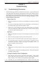
X7DCL-3/i
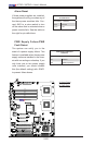
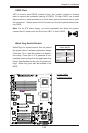
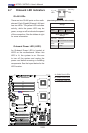
GLAN LEDs
There are two GLAN ports on the moth-
erboard. Each Gigabit Ethernet LAN port
has two LEDs. The yellow LED indicates
activity, while the power LED may be
green, orange or off to indicate the speed
of the connection. See the tables at right
for more information.
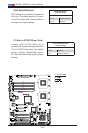
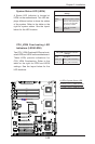
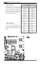
2-7 Onboard LED Indicators
A
B
C
A. GLAN Port1 LEDs
B. GLAN Port2 LEDs
C. Onboard PWR LED
Activity
LED
GLAN Link Indicator
Settings
LED Color Denition
Off No Connection or 10 Mbps
Green 100 Mbps
Amber 1 Gbps
L i n k
LED
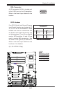
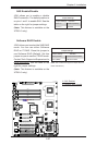
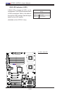
Onboard Power LED (LED3)
An Onboard Power LED is located at
LED3 on the motherboard. When this
LED is lit, the system is on. Be sure
to turn off the system and unplug the
power cord before removing or installing
components. See the layout below for the
LED location.
GLAN Activity Indicator
Settings
Color Status Denition
Yellow Flashing LAN Active
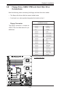
Rear View
(when viewing from the back of the chassis.)