


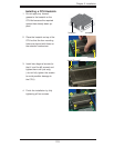
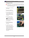

Chapter 2: Installation
2-13
2
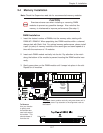
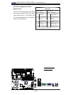
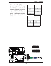
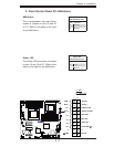
1. Backpanel USB 0
2. Backpanel USB 1
3. Front Panel USB 2
4. Front Panel USB 3
5. Front Panel USB 4/5
6. Front Panel USB 6/7
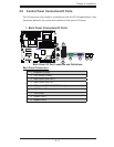
Universal Serial Bus (USB)
Two Universal Serial Bus ports (USB
0 and USB 1) are located on the I/O
back panel. Additionally, six USB con-
nections (USB 2, 3, 4/5, 6/7) on the
motherboard to provide front chassis
access. (Cables are not included).
See the tables on the right for pin
defi nitions.
1
5
6
3
4
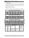
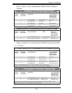
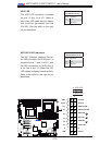
Back Panel USB
(USB 0/1)
Pin# Defi nitions
1 +5V
2 PO-
3 PO+
4 Ground
5 N/A
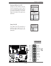
Front Panel USB
Pin Defi nitions (USB4/5/6/7)
USB 4/6
Pin # Defi nition
USB 5/7
Pin # Defi nition
1 +5V 1 +5V
2 PO- 2 PO-
3 PO+ 3 PO+
4 Ground 4 Ground
5 Key 5 No connection
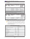
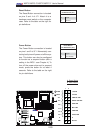
Front Panel USB
(USB 2/3)
Pin# Defi nition
1 Vcc
2 Data-
3 Data+
4 Ground
5NA
X8DT6/E Series Rev. 2.01